• Happy Birthday, Marlene Dietrich (1901-1992)! 🔷😇🦵🏻

Light Weight Solo Tripper Build

Very cool Brian. When you take the strips from the steamer and bend around the mold, are you bending all at once as a single stack, or do you do them individually, laying one on top of the other as you go? Never steam bent wood before so hope this question isn't too obvious.

Thanks
Tony
 
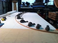
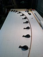
Nice work Brian. Both building and posting. Upgrading to the wallpaper steamer for a steam source is a good move. It was one of the best things I did. I’ve even used it to remove wallpaper. The next upgrade is is to make some drafting weights known as ‘whales’ or ‘ducks’. Saves driving all those nails. But nails work fine. Someone I know has a lot of ice picks and uses them instead of nails. They are faster to set and remove than nails.
59940B90-4870-4198-84F7-0206F56EBCBD.jpeg1334147E-4F44-4655-8B9E-3100D218AD4A.jpeg
Jim
 
Traveler ... the strip stack is bent all at once. Once you remove from the steamer, you have ~40 seconds of bending time, with the first seconds being the most pliable. So being able to place the stack in the bending jig (in this case Stern/Bow molds) and not waste time fastening, just going straight to bending the stack is a solid advantage.

Brian
 
Just a couple of items, then we delve into getting the forms setup, so I can actually start stripping.

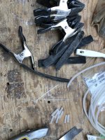
First strip clamping ... I made up 36 of these clamps that Jim Dodd came up with. They have no name currently that I am aware of, so I have gone ahead and named them "Jimmy Clamps", not official, but it is the name I am going to use for these posts .... my hope is that the name sticks.
IMG_1505.JPG

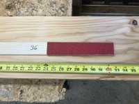
Second are the items I use to do the stem beveling. I also got the idea of a sanding stick from the Michne site. I currently use a couple of flavours.

For this build I made up a new one, this one is 2 wide, with 60 grit one side, 36 grit other side, I use this to do the rough bevel, the 36 grit really does a fast job of doing the majority of wood removal.
IMG_1534.jpg

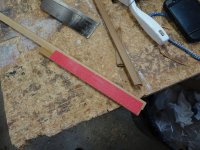
I do the final bevel with this one, which is 2 strips and 60 grit on both sides ... with a small space at the cove side. That space is important if you make one of these. If the sandpaper is lower, you start sanding the strip it is sitting on, not good.
DSC00422.JPG

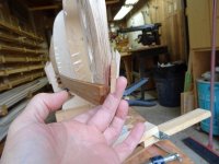
And from a previous build, a shot of how it fits
DSC00425.JPG

Now on to form setup. The form setup supports, start at the strongback center and follow the same regime as described in the post on lofting the shape of the donor boat. The forms are spaced at 12", the loft molds where at 11", this change lengthens the boat to just over 15' (the target length).

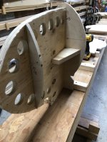
Setting the bow mold assembly
IMG_1539.jpg

I am showing 2 sides, to demonstrate that this form needs a couple of braces to keep it aligned and solid, there is a small footprint that contacts the strongback
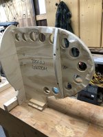
IMG_1540.jpg

Once the bow and stern have been installed, a string is rigged between the center point of each, it is elevated enough that it will clear the highest mold.
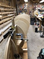
IMG_1543.jpg

Each mold has several lines and reference marks on them, there is a center line mark down one face, this is continued at the top.

Start adding forms from one end, aligning the center of the mold with the center line on the strong back, the top mark gets aligned with the string.
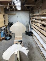
IMG_1542.jpg

To make alignment more finicky, I also add a couple of brackets and make sure it is level side to side.
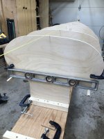
IMG_1544.jpg

And they are all installed

IMG_1546.jpg

One step that I don't have a pic of is each form needs to be vertical, this is usually done by adding a strip running near the top, bow to stern. Nail it to each, then level each form and nail it in place. I did do this, but a strip at the top would interfere with the tie down system I am trying, so there is a support in between the forms holding them level.

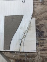
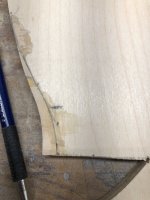
Once all forms are installed, use your eye, fairing strips, whatever you have. Look at the forms to see if they look, is the rate of change between forms, front to back "look" right. I am a firm believer that our sight is very good at picking out anomalies. If it looks good, try laying a strip along the top, along the bilge, along the sheer, do they all look to follow some symmetry.

Doing this I found one form where I had done revision didn't look "right" and needed some adjustment.
IMG_1550.jpg

IMG_1553.jpg

IMG_1554.jpg

One form out a bit is a win in my book, given all the changes and mods done.

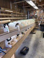
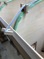
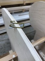
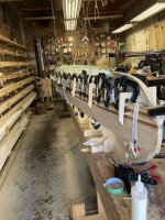
The tie down I am trying are basically rubber tie downs centered on each form. The idea is that it can swing to either side and should be fairly fast and easy to use.

The connecting "thingy" is just bent clothes hanger wire, the center pivot is a 2" #8 cap screw
IMG_1557.jpg

IMG_1558.jpg

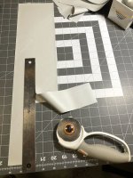
I ordered some Theraband Silver and cut it up into 2" strips for the tie down, and some 3/8" strips to do the wrap/loc used to make a loop at one end around the "thingy" and a larger loop at the other end to go around the form edge ( I have a strip rest there)
IMG_1555.jpg

IMG_1556.jpg

Rather than do a tutorial on how to wrap and attach, if you Google "attaching slingshot rubber band" you will get the idea very quickly.

Getting the first strips on and aligned took quite a bit of time, but here it is ... aligned and first strips on ....
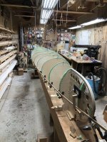
IMG_1563.jpg


Now the fun can begin.

Brian
 
Last edited:
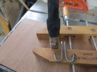
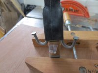
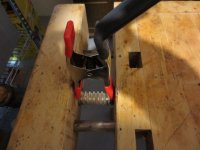
Just a tip on the clamps ! Leave the plastic tips on the clamps, Then stretch the tubing over them. This will make the inner tube last longer, and hold it's position on the clamp better.

I use a couple of bent nails to stretch the tubing over the clamps works great ! Especially with a big bunch of clamps !

IMG_2153_zpsx3isyoy0.jpg

IMG_2153_zpsx3isyoy0.jpg


IMG_2153_zpsx3isyoy0.jpg
 
Good !

By the way ! I wanted to compliment on the lighting in your work shop !

Mine has always been lacking !

At the wood shop we had good lighting, but a trouble light or a Halogen really helped fitting the strip ends in the football.

Have a good weekend !

Jim
 
Those used to be fluorescent, but I swapped to LED last year, according to the light meter, they are giving 3x more light ... and that is at about 1/4 the power.

When I work at night, I realize just how bright they are, because when I step out of the shop ... I am pretty much blind, takes a bit for the night vision to kick in.


Brian
 
This next part will be getting the strips on and writing down some of my thoughts on new stuff (new to me at least) and changes I am trying on this build.

Getting a couple of strips on here, I am already regretting making the strips 7/8" wide ... since I started with 4/4 lumber, I was planing down to make them the right thickness (board thickness = strip width). As I planed and planed, I left the boards as thick as I dared, I just felt bad about making so much sawdust with that great NWC. If I had paid attention to the curves I had designed, I would have realized strips that wide were not going to make some of the curves ... so they got flattened some. If I use this design again, I will use 5/8" width strips ... some extra gluing, but a lot less fussing and seating.

IMG_1565.jpg

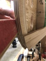
On a positive note, the newer 2" wide sanding stick with 36 grit sandpaper, did a great job roughing the stem bevels, followed by the finer 1.5 strip with 60 grit, coved stick, to the line.

IMG_1573.jpg

If you are building stapleless and there is tumbleholme on the design ... most hold downs that are based on some sort of belt system are not going to be effective until the stripping progresses to the turn at the bilge, so some form of traditional hold down is required to start, I use simple "L" brackets, held by C clamps.

IMG_1591.jpg

Once above that point, they become fairly effective. Obviously the "Jimmy Clamps" go between the hold downs, to provide a tight fit on the strips.

IMG_1603.jpg

Another issue I am dealing with is there's is a lot of curving going on in this design and that requires the strips to bend and stay together, the other decision that is plaguing me some is using the 1/8" radius cove and bead set and opt for the shallower fit. The strips tend to kick out when curving, so the lesson for me is the correct radius cove and bead would have (IMO) held together better in the curves. A little creative handling and I am making it through, but there is a need to be vigilant.

IMG_1593.jpg

This build is using a traditional stem approach, once you get to the level shown in the pic, it is a good idea to start checking how even the strip height is between the sides. If you need matching strips moving up to the bottom ( for accent strips or patterns) if you act at this point, you can just sand a little off the high side cove and adjust the heights to match over a couple of strips.

IMG_1601.jpg

So the take away messages for me so far:

- wider strips are OK if you have a fairly flat, low curve design. As the curves increase, consider strip widths that will actually be able to follow the contours, in this case I think 5/8" would have been best.

- using a 1/4" cove & bead set on 3/16" strips works fine. The cove edges are actually a lot more robust and the strips fit together tight .... on straighter runs. However when presented with a compound curve they will tend to "kick out" and you have to keep a careful eye on that. If you have compound curves in your design, probably best to stick with a set that matches your strip thickness (the deeper bead and cove should hold together better).

- the sanding stick using a 2" wide piece of belt sander belt, glued to a 2" batten works really well to rough bevel the stems, the finish is too rough (IMO) to glue to, so I used it to rough near to the bevel, then used the 60 grit sanding stick to sand to the line.

It is actually moving along well, I do have some filling to do later on, but that is for later on .... right now it is stripping time.


Brian
 
Last edited:
SG,
The other half of my lightening drive (I am not getting any younger, go figure) was to pick up sewing. I made up a new bridge hammock/tarp/quilts last year that are really working for me, as with yours, all down ... even a down back cover for my camp chair.

I figured out I had made a logistical error in being so happy with the new skill, at Christmas my wife brought down her new pajamas and asked me to hem the pants ... I knew I had something wrong at that point.


Brian

Dejavu
 
One reason I route my strips to go Between the bit and the fence ! It's an easy adjustment to alter strip width.

I had one rough sawn plank that varied in thickness from 5/8" - 7/8". I cut the strips.

Next, setting the router to run the strips between the bit and fence, for the bead and cove at 5/8". This unformed them The first pass on the bead side and they were all the same 5/8".

Jim
 
Last edited:
So what contributed to the difference in strip height from side to side ?

Jim
 
Hi Jim, the rough planks varied from ~1" to `1.25" thick (the thickness of each plank was fairly uniform, but each one varied from the others)... they were all planed to make them even, I could do that on the router as you suggest, but I find when using the router, as you increase the amount taken off, you also risk loading and splintering ... so I tend to like to get the plank thickness close to what I want to end up with. Plus rough boards can vary (and most do) along the length, so a light plane to get sides parallel is always a good idea.

I don't think the idea I was trying to convey with the strips has been communicated in this case. The strips are uniform width and thickness, in fact they are really very good at 7/8" x 3/16" x 16'+, so there isn't any issue with the strips.

The issue more fully explained is that I usually like to use 8/8 material, it helps keep the waste down, I will sometimes go with narrower strips, if it means I can get a significant waste reduction. In this case, I didn't feel the 4/4 wouldn't support getting 2 strips per rough plank strip, so I was cutting the boat strips directly from the planed material. As I was taking off material off the planks, converting all that nice NWC to sawdust, I made the decision to stop at 7/8" and use wider strips.

That wasn't a good decision for this boat, the initial tumbleholm section curves a quite a bit and I know from past boats that narrower strips in this area are almost mandatory ... I made the decision based on making best use of the lumber and not necessarily it's intended use ... the end result is that the strips couldn't follow the initial curve because they were too wide.

This necessitated not making that initial tight turn and just flattening the shape a bit, not the end of the world and I think it will look fine, but it was not what I had planned and this is all hindsight.

As I carry on through the build I am trying to share what worked and what didn't, if I had the strips to do over ... I likely would have taken that 1.25" board, planed it level (2 light passes) and then cut 2 strips per plank strip .... then used those narrow boards for the initial tumbleholm turn .... obviously I can't do that now, but someone sharing this build may need to make a similar decision and maybe this will jog their memory and get them to consider strip use when determining how wide to make the strips.

Brian
 
Initially I misunderstood your second question Jim, then a light went on.

I can't be sure exactly what causes strips to get out of sync, but my gut tells me it is that it is easy to put pressure on the strip to push it into the stem, but it not so easy to get pressure to push it down into the cove and bead. After a few strips, you can sometimes see an observable difference between the strips "side to side" and it won't necessarily be the same at both ends.

This becomes more of an issue as you go along, because it can create an area just before the stem which takes a small curve/bend, which can make clamping the strip more difficult. If you keep an eye out for it, a few "lightly sanded cove side strips" can usually fix a small issue, before it becomes an actual problem.

I appreciate you asking, as it drags out build issues that we all face and potentially sets up people to chime in with their own takes and solutions.

Brian
 
I'm impressed with how neat, tight and clean your stripping is progressing! Your strip processing accuracy is paying dividends now. How do you apply the glue? You've figured out the perfect amount!
 
Thanks Rick, you get a feel for the "how much" after a few strips and much cleaning ... at this point I like to get some squeeze out but just enough to form small beads of glue along the strip.

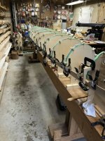
You can see the glue squeeze out on the strip in this pic, and the bottle I use to apply the glue, in the foreground. It is nothing special, a 250 ml Busy Bee bottle with a fine tip. You can also see the line of "Jimmy Clamps" which really work well in keeping the strips tightly clamped.

IMG_1590.jpg

The one thing I like to do, is wait about 10 minutes, the glue skins, then I use either a dull putty knife or a scraper on the joint, the glue just parts and comes right off with no wiping.


Brian
 
Last edited:
A bead of glue about the size of Pencil lead is what I go for..

Small long tips on the glue bottles.

Those bands look like you can adjust the tension. Good !

Jim
 
Thanks for all this detail Brian - very informative. And I too am impressed by the clean strip lines. My build was a yellow, gooey mess once all the strips were laid, requiring many many hours of extra clean-up and sanding. If there is only one thing I can improve for my next build it will be my glueing (well, actually there is a lot more than that on my list, but it is pretty important).

In your summary points above you imply that it would be better to have used smaller than 1/8 radius bead and cove bits to improve the fit for 3/16 strips around tumblehome and curves etc. Can you actually get bead and cove smaller than 1/8 radius? I haven't been able to find any and curious if you know of a source.

Thanks
Tony
 
Hi Tony, I am going to take a pic of the glue in the cove, which I don't typically do ... Jim's explanation/description is pretty accurate, but a pic is sometimes worth a lot of words.

The 1/8" radius is for 1/4" profile, you can get 3/32" radius bits, which will give you the 3/16" cove and bead I was mentioning.

A source for Beading Bit, also known as a Bull Nose https://www.freudtools.com/products/82-100

And the Coving Bit, also known as a Fluting Bit https://www.freudtools.com/products/99-030

I am sure there are quite a few others, with router bits it can take a bit of looking as the names seem flexible from vendor to vendor ... I know I also looked up another set that was 3 coves and 3 beads on the same bit, which would also work fine.

Brian
 
Back
Top