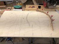
For this project I need to get a starting shape and that means transferring the shape of the selected canoe (in opening post) to tables or molds or both. I am going to transfer the basic shape to a tabular form and then modify most of the shape parameters (bow/stern/width/length) to meet the criteria I have in mind for this build, then use that to create the molds for the build.
Over the past few years I have noticed a few posts asking about lofting, both "How to loft from tables to make canoe molds" and also "How to transfer a canoe shape to molds" ... I didn't find many posts covering the subject, I wrote a detailed one for transferring from tables of offsets to make the molds (link at end of post).
So this post will cover the method I used for creating a table of offsets for a given canoe shape, using the strongback and a few simple jigs. I would stress that it is not my intention to make a copy of the canoe, it is to get a starting point from which I will be changing the width/length and bow/stern profiles.
The starting canoe is 14' long and I have decided to use 15 molds, spaced at 11" apart to capture the shape. The whole operation will use the strongback as a work platform as it is designed just for these types of operation. It may create confusion, when I am trying to simplify, but when I say "mold" in this description, it is actually referring to the measuring jig that is being placed where a mold/form would sit when building a boat.
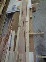
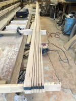
1. Mark the center of the strongback and align the middle mold support so that the mold will straddle the center line. You want the center of the mold to line up with the center line of the canoe. Obviously, this will vary somewhat with the materials being used, but I am only presenting the method, it would need to be "tweaked" to suit the shop it is being used in.
2. Draw lines every 11" from center, 7 towards the bow and 7 towards the stern ... you will have ~6" leftover from the bow/stern markers.
3. Install a mold support at each line, the support is installed on the side facing away from the end of the boat you are traveling towards. e.g. If you are doing the ones on the bow side of center, put the supports on the stern side of the lines.
4. Halfway to the stern and bow from the center, place a pair of supports for the boat, they need to be wide enough to extend beyond the gunnels at that point by a few inches and tall enough to clear the measuring jig at both the stern and bow (more on that in a few lines)
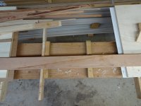
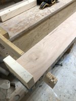
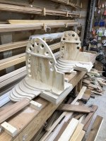
The supports are nothing fancy, here is a shot ... I believe it needed to be about 9 " high. You may need to adjust the individual heights, shimming will only take you so far.
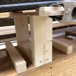
Adjust the supports so that a level placed on the center line of the boat (at the center) looks level, the ends will have a gap as the rocker will show, but the main center area should be about level .... not essential but desirable.
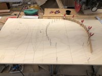
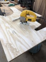
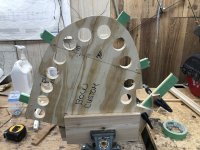
5. You need to make up a "measuring jig" from a rigid material, I used 12 mm baltic birch. It looks like this :
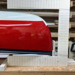
mine was 26" high x 24" wide, the beam is 4" wide, providing lots of rigidity. The vertical and horizontal pencil marks (every inch) were drawn in before the cut out was made, insuring all the lines were related. A note here, the bottom and outside vertical are factory lines, the top is parallel cut to the bottom line to preserve the factory alignment .... this is a pretty important point.
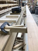
The jig did not need to be 24" wide, I wanted the base to extend and cover the entire strongback top to provide the best support and alignment. To help align the jig with the boat, I also placed stop blocks on the strongback which the jig fits into and a stop block on the measuring jig, so that it slides in and stops at the same place at each mold station.
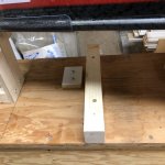
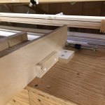
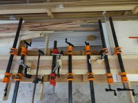
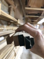
6. Lock the canoe in place, so that it is centered on the strongback, side to side and fore and aft. Make up 2 centering blocks as shown in the pic (bow and stern), have then marked with a center line, install on the 14' mark length wise and on the strongback center line side to side (center of block to center line on stronback). Once installed at both ends the canoe is locked in place and the top center line can be determined. Just a note, those little keeper blocks do not let the canoe move side to side, they are snug.
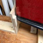
7. Attach a stiff vertical batten to both of the centering blocks, run a string between that lines up with the strongback center line (or if the canoe has a center line marked i.e. mold line or some sort of joint that may be easier to use). Put a piece of masking tape down the center of the canoe. Now measure between the battens, and make a mark at the center of the canoe on the masking tape. Make side to side (large hash) marks every 11" along the masking tape, then go back and looking down make a mark (bow to stern) at each mark, effectively making a cross hair at each mark. These marks should be aligned with the strongback and mold layout. So we have a way to align the bottom of the measuring jig and the top to a common alignment.
Will look like this
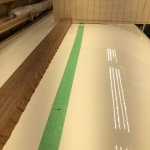
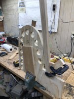
8. After all of that (it is wordy, but overall not very complicated) we are ready to take some measurements. Slide the measuring jig into place and make sure it is flat against the strongback top. Push it in to the stop and lightly clamp, adjust as necessary to align the top marks side to side.
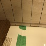
For those of you noticing that piece of jatoba sitting there with anti skid cloth under it, and wondering why it was there ... it was used to push the measuring jig forward and aft as required to get the alignment right. Once you have the jig lined up both ways, we measure. Recycling a pic, this is what it looks like when you are ready to measure
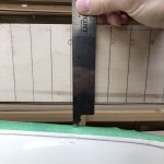
9. We are going to collect 2 sets of data, the "Waterline" and "Butt" data refer to what the values describe. Butt data is measured from the "Baseline" down (down being towards the canoe bottom) ... which is confusing as we always see the canoe upside down on the strongback and will think of the number as up, these are the values from the horizontal arm. Waterline is measured from center of the boat out, values from the vertical arm.
Basic measuring process Butt:
Align a ruler with the line and let it rest on the canoe surface, measure the exact distance to the top of the jig and record this value. Subtracting this value from the jig height of 26" gives you the boat point above the strongback. It's a little hard to see in the pic, but the line that aligns at the center is labelled as 0 and each corresponding line is 1 ", so I took measurements every inch. Record the position and measurement at each line, i.e. 0, 5 1/2", this would translate into 20 1/2" at 0 (26 - 5 1/2) ... so if this was station 7, you would record in the butt table 0, 20.5
Repeat at each inch marker until you are about halfway around the turn of the bilge, record all values under the Butt list for that station
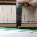
Basic measuring process Waterline:
This is a little different as we will also getting the sheer values
1. Measure up from the bottom of the jig to the top of the gunnel, that is the sheer height for the mold, record as ...... station , sheer
2. Measure from the side of the canoe to the edge of the measuring jig. As with the Butt measurements, subtract the measured value from the distance of the center line to the jig side edge.
3. Vertical measurements start at the inch marker above the already recorded sheer lines, continue until you reach the turning point at the bilge
I overlapped the 2 sets of measure by about 2 points, so that it showed they aligned the same (overlapped points have a line with them to denote which are which on the overlap). I entered these values into a spreadsheet to convert them to co ordinates I could use, but it could be easily done on paper as well. The Butt values for this technique are describing the hull bottom and the Waterline values are describing the vertical hull shape including the sheer
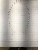
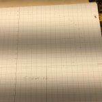
To check your measurements or to plot your values, I plot them out on paper (use whatever tools you have) like this (also covered in the lofting at the end of post):
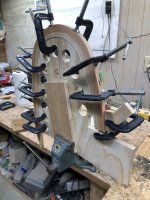
To do the bow/stern profiles, just re orientate the measuring jig against the last mold like this:
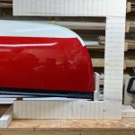
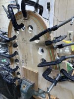
Perform similar measurements like this:
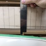
Looking at the measuring pic, it is for the bow profile ... you can see the skid plate, don't forget to subtract it's thickness from the profile. A good guess ( mine was ~3/32") should be sufficient, as it is subtracted from each measurement. Also on the bow/stern profiles, if you intend on using stems, they need to be adjusted to allow for the stems.
This method seems to be good for about 1/32" and I believe it is plenty for purpose. i wasn't trying to do a tutorial, just a rough out of the method I used, I did delve a little deeper than this, but anyone trying this will need to adapt to the tools, skill set and shop available, so it didn't make sense to put in too much detail, you can always ask for clarification or more details.
Once I had all my data entered and developed my spread sheet to work with the data, I spent quite a bit of time "playing" with the shape, redesigning the bow/stern, finding suspicious values and going back to recheck measurements. Overall I likely spent 20 hours getting things to the way I wanted, but they did seem to work out well.
If you haven't lofted from tables, I did do a post on that as well here:
http://buildersforum.bearmountainboa...php?f=9&t=4658
Brian

