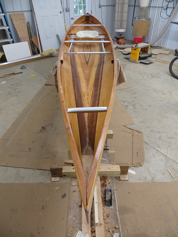
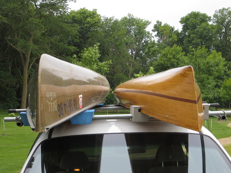
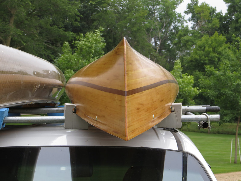
OK, let's do the foot brace. This is going to be long and picture intensive.
The standard adjustable foot brace is usually aluminum angle riveted to the hull with lots of holes drilled in it and a thumbscrew holds the foot brace in place. To change position it's a simple matter of unscrewing the thumbscrew and moving the foot brace to another hole. The problem is that this is pretty much impossible to do on the water so if you slide your seat to adjust trim or for water conditions your foot brace is now at the incorrect distance. Many newer racing canoes have a foot brace integrated with the seat. The foot brace slides in tracks mounted to the side of the hull with rods running from the foot brace to the seat. So when the seat moves the foot brace moves at the same time, sliding in the track.
So how do I recreate something like this while keeping it relatively simple and use the parts I have available? I mulled it over for a couple days and came up with what I thought was a workable idea but I really doubted I'd be able to pull it off. I was sure at each step that the whole plan would fall apart but it just kept working.
First thing I needed was a t-slot. But I don't have a t-slot cutter for my router and neither does anyone else in town. And of course you know I don't want to order one and wait for it to get shipped here. Thought about using pre-made t-slots used for woodworking benches but the one small one I have wasn't long enough to do both sides and was surprisingly heavy. Finally I had an idea.
Start with a cedar railing spindle:
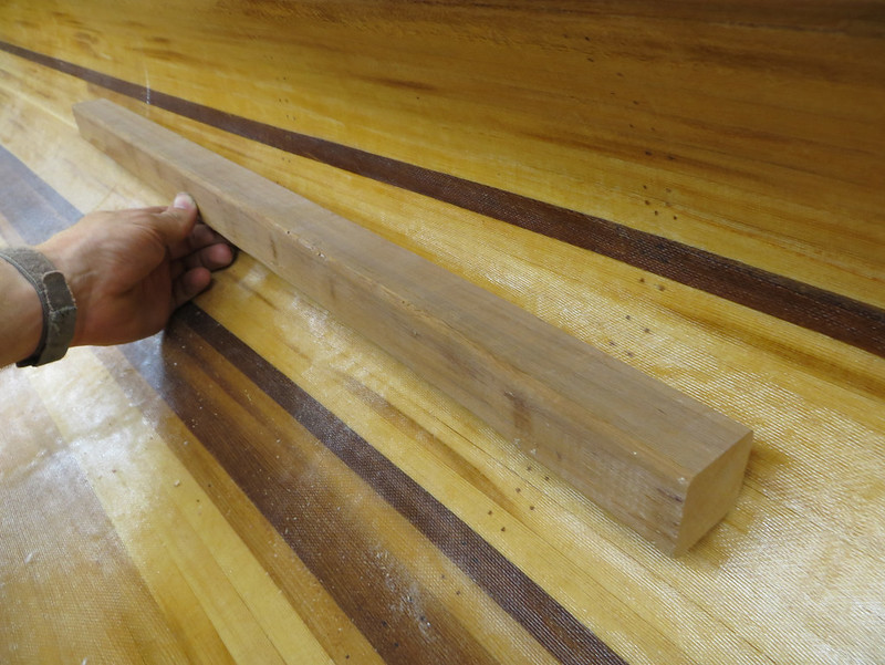
20140731_001 by Alan Gage, on Flickr
Cut an angle. Test fit. Cut a little more angle. Test fit. Repeat.

20140731_002 by Alan Gage, on Flickr
Hey, that's pretty close! A belt sander can do the final shaping from there. Just shave off where it hits the hull until the gaps are gone.

20140731_004 by Alan Gage, on Flickr
So step one is complete. I can actually cut a board that will fit tightly agains't the hull. Now for the slot.
Rip those same boards in half:

20140731_005 by Alan Gage, on Flickr
Cut a dado on the matching faces of each piece:
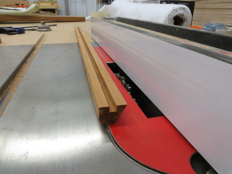
20140731_006 by Alan Gage, on Flickr
And then glue them back together. Now you have a board with a rectangular hole running the length of it. I gave the dados a light coating of epoxy to seal them before gluing the boards back together.

20140731_008 by Alan Gage, on Flickr
If this looks hard it's not. Just some quick and dirty measuring and a fair amount of, "that looks like about enough."
Now for the fun part. Set the saw blade so it will just reach the rectangular hole you made and make a rip right along the glue line. I did two passes to get it the width of 1 1/2 blades:

20140731_009 by Alan Gage, on Flickr
Tada! Instant t-slot. Well....maybe not instant....but it's a t-slot anyway.
Phase 2 complete. Now I need to figure out how to get the foot brace to slide in this slot.
Cut a couple inches down the center with a hacksaw:

20140731_010 by Alan Gage, on Flickr
Smash flat with hammer:

20140731_011 by Alan Gage, on Flickr
Now you see where I'm going, don't you?

20140731_012 by Alan Gage, on Flickr
Uh oh, it's too thick to slide smoothly through the slot

20140731_013 by Alan Gage, on Flickr
So lets cut one of those legs off and then cut a small slit down the remaining one.

20140731_014 by Alan Gage, on Flickr

20140731_015 by Alan Gage, on Flickr
After filing down the tabs it fit. Looks doable so it's on to the next step, epoxying the guides to the hull. This is where I stopped and gave it another day of pondering. I really didn't want to glue anything to the hull only to have it not work and it be unremovable. But I decided that even if my grand scheme didn't work I could always attach a standard foot brace to the top of the guides where there is a wide flat section. So the next evening I bit the bullet and glued them in place. There was no good way to hold them there while the epoxy setup so I just wedged in a couple pieces of scrap. That seemed to work:

20140801_012 by Alan Gage, on Flickr
At this point I still don't know if the foot brace will slide smoothly through when done or how I'm going to attach it to the seat. I'm just hoping I can come up with something workable when I get to each new step.
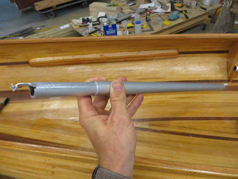
So that gets us to this morning. Started by rough shaping the ends of the foot brace:
20140802_002 by Alan Gage, on Flickr
The ears needed to be shorter, the flat section needed to be flatter, and I needed to angle the edge so that it matched the angle of the hull. With the end squared off it would bind. All this was done with the fancy tools I showed in a previous post on making the thwarts as well as these specialty items:

20140802_005 by Alan Gage, on Flickr
The upside down belt sander on the floor was great for rough shaping the ears. The file smoothed everything out.
And here's the final profile:

20140802_019 by Alan Gage, on Flickr

20140802_020 by Alan Gage, on Flickr
So how does it work now? Well it slides but it tends to bind quite a bit. When doing it by hand I have a hard time keeping the bar straight across so it binds. I don't know if it will be better or worse once it's connected to the seat:

20140802_003 by Alan Gage, on Flickr
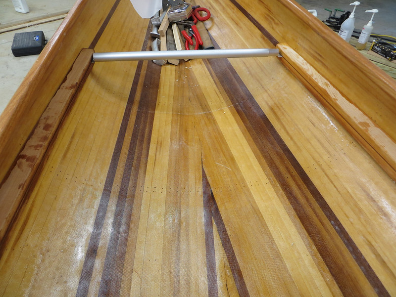
20140802_004 by Alan Gage, on Flickr
So now I need to connect it to the seat. I bought a few different pieces of aluminum hoping something would work. I had some thin rod but that was pretty delicate and I couldn't think of a good way to connect it or make it adjustable. I had some aluminum channel but that was kind of heavy. Figured I'd start with aluminum angle and see how that worked. I drilled one hole 1" from each end and bolted it place for the first trial:

20140802_006 by Alan Gage, on Flickr
And that turned out to be the only trial necessary. It couldn't have worked any better. I was shocked. I really thought that I'd spend all day working on this and in the end have to scrap the whole thing. It wasn't even noon yet! I was pretty excited and did a lot of yelling and dancing around.
Another link to the same video posted in the above reply if you want to see it in action (sorry, no dancing or yelling): https://www.flickr.com/photos/7935459@N05/14624008430/
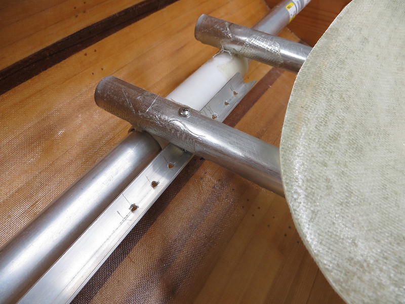
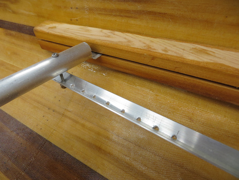
I then drilled holes every 3/4 inch to give me 5" of adjustment in the front and rear:
20140802_011 by Alan Gage, on Flickr
20140802_010 by Alan Gage, on Flickr
I decided on 3/4" spacing for the holes because a piece of 3/4" wood made it really easy to layout each centerline to drill. I would have preferred to have all the adjustment on the seat end but once to go past 5" it's sticking out behind the seat frame and hits the bulkhead when the seat is slid back all the way. So if someone short uses the boat they can get the rest of the adjustment on the foot brace end.

20140802_012 by Alan Gage, on Flickr
So that's it. Now the real test will be to see how it actually performs on the water and how it stands up to usage over time. The aluminum angle would easily bend if stepped on but it's close enough the hull that shouldn't be an issue unless I stumble when entering the boat or something. The thin flat section on the foot brace will be weak too but, again, hopefully it won't see stress in that direction. It won't during normal use. And hopefully if either of those are stressed they'll bend before they break something else.
Alan
The standard adjustable foot brace is usually aluminum angle riveted to the hull with lots of holes drilled in it and a thumbscrew holds the foot brace in place. To change position it's a simple matter of unscrewing the thumbscrew and moving the foot brace to another hole. The problem is that this is pretty much impossible to do on the water so if you slide your seat to adjust trim or for water conditions your foot brace is now at the incorrect distance. Many newer racing canoes have a foot brace integrated with the seat. The foot brace slides in tracks mounted to the side of the hull with rods running from the foot brace to the seat. So when the seat moves the foot brace moves at the same time, sliding in the track.
So how do I recreate something like this while keeping it relatively simple and use the parts I have available? I mulled it over for a couple days and came up with what I thought was a workable idea but I really doubted I'd be able to pull it off. I was sure at each step that the whole plan would fall apart but it just kept working.
First thing I needed was a t-slot. But I don't have a t-slot cutter for my router and neither does anyone else in town. And of course you know I don't want to order one and wait for it to get shipped here. Thought about using pre-made t-slots used for woodworking benches but the one small one I have wasn't long enough to do both sides and was surprisingly heavy. Finally I had an idea.
Start with a cedar railing spindle:

20140731_001 by Alan Gage, on Flickr
Cut an angle. Test fit. Cut a little more angle. Test fit. Repeat.

20140731_002 by Alan Gage, on Flickr
Hey, that's pretty close! A belt sander can do the final shaping from there. Just shave off where it hits the hull until the gaps are gone.

20140731_004 by Alan Gage, on Flickr
So step one is complete. I can actually cut a board that will fit tightly agains't the hull. Now for the slot.
Rip those same boards in half:

20140731_005 by Alan Gage, on Flickr
Cut a dado on the matching faces of each piece:

20140731_006 by Alan Gage, on Flickr
And then glue them back together. Now you have a board with a rectangular hole running the length of it. I gave the dados a light coating of epoxy to seal them before gluing the boards back together.

20140731_008 by Alan Gage, on Flickr
If this looks hard it's not. Just some quick and dirty measuring and a fair amount of, "that looks like about enough."
Now for the fun part. Set the saw blade so it will just reach the rectangular hole you made and make a rip right along the glue line. I did two passes to get it the width of 1 1/2 blades:

20140731_009 by Alan Gage, on Flickr
Tada! Instant t-slot. Well....maybe not instant....but it's a t-slot anyway.
Phase 2 complete. Now I need to figure out how to get the foot brace to slide in this slot.
Cut a couple inches down the center with a hacksaw:

20140731_010 by Alan Gage, on Flickr
Smash flat with hammer:

20140731_011 by Alan Gage, on Flickr
Now you see where I'm going, don't you?

20140731_012 by Alan Gage, on Flickr
Uh oh, it's too thick to slide smoothly through the slot

20140731_013 by Alan Gage, on Flickr
So lets cut one of those legs off and then cut a small slit down the remaining one.

20140731_014 by Alan Gage, on Flickr

20140731_015 by Alan Gage, on Flickr
After filing down the tabs it fit. Looks doable so it's on to the next step, epoxying the guides to the hull. This is where I stopped and gave it another day of pondering. I really didn't want to glue anything to the hull only to have it not work and it be unremovable. But I decided that even if my grand scheme didn't work I could always attach a standard foot brace to the top of the guides where there is a wide flat section. So the next evening I bit the bullet and glued them in place. There was no good way to hold them there while the epoxy setup so I just wedged in a couple pieces of scrap. That seemed to work:

20140801_012 by Alan Gage, on Flickr
At this point I still don't know if the foot brace will slide smoothly through when done or how I'm going to attach it to the seat. I'm just hoping I can come up with something workable when I get to each new step.
So that gets us to this morning. Started by rough shaping the ends of the foot brace:

20140802_002 by Alan Gage, on Flickr
The ears needed to be shorter, the flat section needed to be flatter, and I needed to angle the edge so that it matched the angle of the hull. With the end squared off it would bind. All this was done with the fancy tools I showed in a previous post on making the thwarts as well as these specialty items:

20140802_005 by Alan Gage, on Flickr
The upside down belt sander on the floor was great for rough shaping the ears. The file smoothed everything out.
And here's the final profile:

20140802_019 by Alan Gage, on Flickr

20140802_020 by Alan Gage, on Flickr
So how does it work now? Well it slides but it tends to bind quite a bit. When doing it by hand I have a hard time keeping the bar straight across so it binds. I don't know if it will be better or worse once it's connected to the seat:

20140802_003 by Alan Gage, on Flickr

20140802_004 by Alan Gage, on Flickr
So now I need to connect it to the seat. I bought a few different pieces of aluminum hoping something would work. I had some thin rod but that was pretty delicate and I couldn't think of a good way to connect it or make it adjustable. I had some aluminum channel but that was kind of heavy. Figured I'd start with aluminum angle and see how that worked. I drilled one hole 1" from each end and bolted it place for the first trial:

20140802_006 by Alan Gage, on Flickr
And that turned out to be the only trial necessary. It couldn't have worked any better. I was shocked. I really thought that I'd spend all day working on this and in the end have to scrap the whole thing. It wasn't even noon yet! I was pretty excited and did a lot of yelling and dancing around.
Another link to the same video posted in the above reply if you want to see it in action (sorry, no dancing or yelling): https://www.flickr.com/photos/7935459@N05/14624008430/
I then drilled holes every 3/4 inch to give me 5" of adjustment in the front and rear:

20140802_011 by Alan Gage, on Flickr

20140802_010 by Alan Gage, on Flickr
I decided on 3/4" spacing for the holes because a piece of 3/4" wood made it really easy to layout each centerline to drill. I would have preferred to have all the adjustment on the seat end but once to go past 5" it's sticking out behind the seat frame and hits the bulkhead when the seat is slid back all the way. So if someone short uses the boat they can get the rest of the adjustment on the foot brace end.

20140802_012 by Alan Gage, on Flickr
So that's it. Now the real test will be to see how it actually performs on the water and how it stands up to usage over time. The aluminum angle would easily bend if stepped on but it's close enough the hull that shouldn't be an issue unless I stumble when entering the boat or something. The thin flat section on the foot brace will be weak too but, again, hopefully it won't see stress in that direction. It won't during normal use. And hopefully if either of those are stressed they'll bend before they break something else.
Alan
Last edited:


