• Happy Apple Cider Day! 🍎🍵

New Solo Daytripper Design & Build

Joined
Mar 21, 2015
Messages
530
Reaction score
115
Location
SW Wisconsin/Driftless
So, my last couple of shop days I've been spending some time on a new build Solo Daytripper. I was somewhat disappointed in my previous solo build, and have found that even with ballast and careful trimming my tandem is far too large for me to daytrip comfortably.

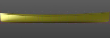
I sketched up a new design:
Delft_Right.JPG

Delft_Front.JPG

This one is fairly small.

Length: 13' between verticals, just a little rake to the stems so about an inch less on the 3.5" WL
Gunwale Beam: 23"
Shoulder Beam: 27"
3.5" WL Beam: 21.8"

Both a little longer and narrower than a Wee Lassie II.

Rounded midpoint bottom, shifting into a v-hull in the ends.

Asymetric hull, slightly swede-form with the wide point about 10" back of dead center. This shifts the CB back about 4" from center. Slightly (very slightly) more rocker forward.
 
And I actually started building the thing over my last couple of shop days in between other projects.

Laying_Out.JPG

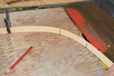
Used a few less reference points for these than I have in the past and got some very good results. In addition to the Gunwale, Shoulder, and bottom center points, I only marked in the 3.5" WL and the width 1/2" above the center point. With the rounded curves that I was using, this splined out very nicely.

Shoulder_Splined.JPG

Not sure if I got lucky or what, but I only had to spend a couple of minutes joggling forms to get them properly aligned on the strongback. No need to push them forward, back or tilt. Just made sure the centerlines match and are vertical. That shoulder curve faired in very pretty, I think.

Splines_Mess.JPG

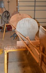
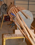
Now it appears that I've made a mess here. This is what happens when your family wants their garage back before bedtime: You need to stop mid-project.

You may have noticed that I've only got three forms here. I'll leave you to speculate for a while on what I may be up to.
You may also have noticed that I've not taken many pictures. You're right, I've gotten out of the habit. Also, I seem to take very poor pictures when I'm in the shop.
 
Looking forward to this build, sailsman, and the hundreds of pictures you will undoubtedly take for the instruction of future generations and to preserve a bit of your own life history.

3.5" WL Beam: 21.8"

Wow, that's ultra-narrow! Is this going to be a sit-on-bottom pack canoe? That's narrow even for a pack canoe.
 
I'm guessing you are making a one off, male mold, for a composite.
Maybe foam /Plaster Paris, construction?
 
So, bit later update than anticipated. First, I forgot to respond to this question:

Wow, that's ultra-narrow! Is this going to be a sit-on-bottom pack canoe?

Very much in the spirit. I'm not sure if it will quite qualify - we'll see how the weighting turns out. Intended as a day boat. I won't say it's impossible that I would ever camp out of it, but focus on getting on local water on short notice. I'm hoping for a nimble hull that has good glide. Less focus on portageability. If not seated exactly on the bottom, I'll be pretty close to.

@Jim Dodd I can see how you might think that, but that's not where I'm going.


Now, remember that I suggested Destruction and Warning as part of the possible things to be learned here? Well, a question for you: Have you ever gotten a bit down a pathway on a project and realized that you took a wrong turn and need to backtrack? I had one of those this week.

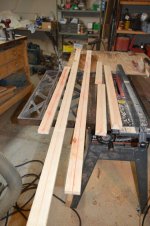
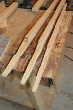
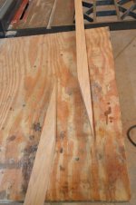
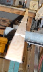
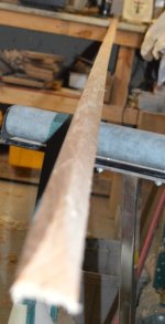
Thursday I created this, starting with some rough-cut pine that has been in the barn for ages:
Rough_Pine.JPG
Cut_Pine.JPG

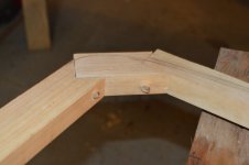
Even attempted some fancy joinery:

Pine_Joint.JPG
Pine_Pegged_Stem.JPG

Only to realize that some of the issues that I was running into while working with the stuff would carry over into the finished build no matter what I did.


Today (yesterday? I'm a night owl) I scrapped it, and started over in hardwood.

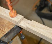
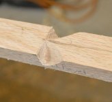
Simpler joinery this time:
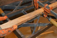
Oak_Scarf_Cut.JPG

Oak_Scarf_Fastened.JPG

Sort of a hybrid fastening method here. The glue is TiteBond III. The nails are the species known as "Cement Coated Sinker". (Somewhat hardened steel, with a PVC adhesive on the surface - The friction of driving them literally hot-glues them in place so they don't work out.) I might replace them with another pin method, but they do function. They take a lot of the loads that would translate to sheer or peeling on the glue joint.

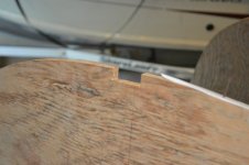
Some modifications to the forms: (This was planned from the beginning, and was done to all forms)
Form_Notch.JPG

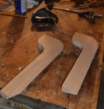
Some more parts:
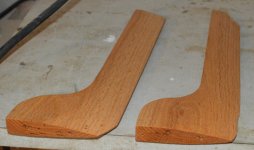
Stem_Blanks.JPG

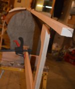
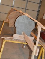
Temporary fitup to mark how everything goes together and spline some dimensions:
Stem_Fitup_1.JPG
Stem_Fitup_2.JPG

(Yes, some things were removed to make access easier.)

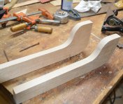
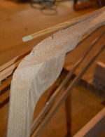
Then back to the bench for some shaping using a solid surface:
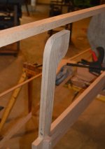
Stems_Shaped.JPG

More of this to come, this is just where I had to stop for the evening.
NB: Don't worry about the chewed up end on the one. It's long enough to be in full contact with the strongback, but will be cut down by about 2 1/2" for final install.
 
So... Last week was pretty full. Didn't get to work on the build. This week, I might get two shop days.


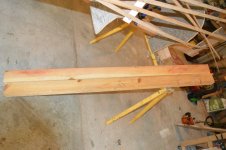
A backbone/keel timber isn't much use if it's just a rectangular cross section...
Mid_Bevel_Mark.JPGEnd_Bevel_Mark.JPG

Made some plunges with a handsaw and chisel at strategic points to mark out what I need.

Bevel_Marked.JPG

Yes, there's a bit of wayne in that. Not sure how it happened. It's flexible enough that I expect it to be worked out later in the build.

Winding_Bevel.JPG

And some power plane for roughing out and a handplane to finish, and I have winding bevels. This is an awful picture. I may replace it with another later. Poor lighting and forgetting to check some of the camera settings.

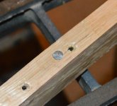
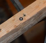
And I started the process of replacing the heavy sinker nails that were in the scarf splice:

Head_Side.JPG
Rivet_Side.JPG

I'll fix the previous holes later. Interesting thing: If you look through a lot of specs for various standard style fasteners, you find things that sort of fit together, even though they are not intended to be combined. This is a 6D box nail, and an M2.5 flat washer. "Box nails" as well as "Common nails" are very soft mild steel that can be cold-worked very easily, and this size washer is a slightly loose fit. It rivets down beautifully if I get the length right. Need a better tool to cut them. I think a diagonal cutter (for clearance - you don't want a lot of extra length on these) with a compound hinge for leverage. (like the hinges on a bolt cutter)
 
Are you making a dacron canoe?

I can see how you might think that... both the previous post and tonight's do show parts that could be for a Skin-On-Frame. However, I'm not doing any flavor of SOF, dacron or otherwise this time around.

(I promise I'm not framing the photos to be misleading. This is just the order the components are being created in.)
 
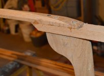
After fairing down some parts, I realized that there wasn't enough meat for tying in the stem pieces. Well, guess that means a bit more TiteBond.

Stem_Built_Up.JPG
(Note that the exposed screw head is temporary. Sometimes the best clamp is a fastener.)

Keel "Timber" - really? Keel twig? Something? back on the strongback.

Keel_timber.JPG
It was kind of amazing how this assembly felt rather like moving a boat while bringing it back to the forms...

Anyway, I faired in the ends of the keel... piece in place:
Trimmed_Ends.JPG

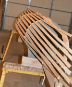
And I'm back at this... situation:
Mostly_Splined.JPG
 
Some projects motivate you to build jigs or tooling that you've been putting off.
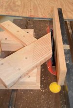
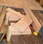
Feather_1.JPGFeather_2.JPG


I thought this little featherboard set turned out well enough that I'll keep it around. And yes, that is a 7 1/4" ultra thin blade mounted in a full size table saw. It's great for rough ripping - Hot knife, butter, you've heard it before.

Here's the reason that it's boosted off the tabletop: I wanted the featherboard pressure to be above the fully extended blade.
Feather_Use.JPG

Unfortunately, this is the only part that went well. That particular plank was too wide to handle with just this arrangement, and the bandsaw refused to follow the existing cuts as planned. (I've never had any luck tuning a bandsaw for resawing operations, which is why I didn't start with the bandsaw.) Lost two out of four thin pieces. :( Well, try again with some modifications...


Now, the question is: why do I need to resaw stock for this canoe? :D
 
Last edited:
Lapstrake?
Yes, indeed! I've privately been calling this one "The Viking Build" pretty much since its inception.

Now that it's out there, I'll try to include a little bit more about my thought process in future posts.

I will say that the resaw from the last post was for the Garboards/Gar Planks. They will be the widest piece on the canoe, so no need to strain my resaw capabilities for future parts. I was actually able to salvage what I needed from the "Ruined" pieces. I only need a limited length in addition to the clean planks that I'd already gotten, and enough of the messed up pieces survived intact.
 
So, yesterday turned out to be all those niggling little bits that seem simple but end up eating a lot of time.

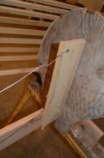
I found that my strongback arrangement wasn't quite as stiff as I'd thought. Future builds along these lines (if this one works out well) will need a bit of a rethink for the back. In the interim, some tensioned wire will do the trick.
Wire_Far.JPGWire_Close.JPG

First time I've had the fencing pliers out in a while. The strongback was sagging vertically, and was warped to one side, hence two wires. Also, yes... I do use pretty much every available plank edge for clamp storage. Why do you ask?

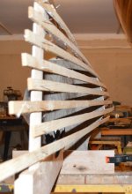
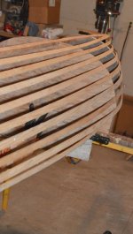
I also ended up fine-tuning the location of the forms, and making sure the battens were fair.

(All Y'all might be getting sick of batten shots. I promise these are the last ones that don't have another feature in them, but this is the first time I've had the full hull form completely faired in at full scale. I think it looks pretty! What about you?)
Faired_End_Low.JPGFaired_Wide.JPG

Faired_End_High.JPG

If you're noticing the burble in the second batten out from the center, I am aware. The "cheek" of the transition between the stem and the keel timber isn't feathered far enough back. (It's rather hard to shape wood without a solid backer) After this shot, I took the keel down to work on it on the bench and to get some finish on it. That end will now flow much better.

Not shown in the pictures: I used the raw garboard stock as a stiffer spline to confirm that the winding bevels I had cut on the keel-piece had a fair enough transition to settle in properly when fastened.
 
So, a little bit of detail for those curious - or perhaps a little bit confused about how this is all supposed to work.

The methods I'm using here are a combination of some traditional lapstrake (AKA "Clinker") techniques and some notions that I borrowed from Thomas J. Hill's "Ultralight Boatbuilding". Each of the battens - and yes, they are cedar strips leftover from previous builds - lines out where one of the plank edges will be.

  • Total of 9 planks per side: 1 Garboard, which is the wide plank right on the keel, 7 "normal" planks, and the in-turned plank above the knuckle. (Typically, the top plank is called the "Sheer Plank", but with that hard shoulder chine, I'm not sure if that's quite accurate.)
  • Like a traditional Clinker build, Each each batten will be used to spile the appropriate plank, and then be removed to make room to actually install the plank.
  • From ULBB, I will be directly marking out the planking stock on the forms. Traditional Clinker builds have a variety of ingenious tricks and mechanisms for templating out the shape of the plank from the reality of three dimensions to the two-dimensional planking stock. This is handy when your planking stock is large, awkward pieces of heavy dimensional timber. When I will probably be able to lift the entire stock of planking blanks over my head with one hand and pinch clamps are sufficient to hold everything in place... Each plank will be marked out by the edge of the previous plank, and the edge of the current batten.
  • I will only be running battens on one side of the forms. I'll mark out and cut a pair of planks with one setup, and then install them as mirror images on both sides of the hull.
Thoughts? Questions? Feel free to share.
 
So, not a lot of exciting photos from Monday.

I got some Boiled Linseed Oil on the stems and keel timber: Not much for pictures:
Finished_Stems.JPG

My dad also helped me run through the rough stock pile for planking blanks, as well as some stuff for an unrelated project, which I really appreciate - doing this part solo would take a lot longer.

For those that have never experienced it, watching a pile of rough lumber transform into something recognizable can be quite a trip. Also, the pile always shrinks. This pile started just as it came from the sawmill, then surfaced on both sides. (Planer)

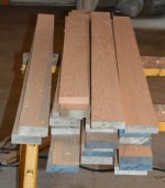
Planks_Rough.JPGPlanks_Planed.JPG

Unfortunately, most of the stock we had was just a little too thin for me to be confident that I could resaw three plank thicknesses out of it, so more got turned into sawdust and planer shavings than I would have liked, but what do you do?

Note that the two extra-thick planks from the first two photos didn't get resawed. (I hope I don't need them)
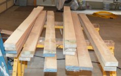
Planks_Resawed.JPG
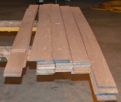
So there it is: 200+ linear feet of plank stock, 7/32" thick (about 5.5 mm) by roughly 3 1/2" wide. This should do about the whole canoe except for the sheer/gunwale plank, which is going to be wider and I think a little thicker.

The planks will each have to be cut out to a curve, so a good bit of this is still going to be scrap.
 
Back
Top