• Happy Birthday, Stan "the Man" Musial (1920-2013)! ⚾🐦

Multiday Adventure Race Canoe - Composite

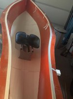
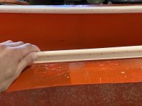
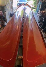
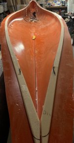
I still have to polish the mold, but I thought I'd get started on the gunwales. It's a milestone because it is the first time I am working on something that will be part of the final boat. The gunwale profile I successfully tested is an "L" shape that sits on the top edge of the mold. I milled them from a sheet of 3/8" PVC foam (5lb divinycell). First, I cut 1" strips (horizontal component) on the band saw, then ran them through the router to round off three of the edges. The vertical component was made by cutting a 3/4" strip, then cutting one end at a 45degree chamfer to blend flush to the hull. This would be easy to assemble if the canoe edge was 90degrees along it's length- but in fact the hull meets the top flange at a an angle that varies along the length of the hull. So I taped the vertical piece along the hull, and cut the top flush with the top flange. Then I glued on the top component- using a heat gun to bend the strips as required. Sewing pins held it together while the glue dried. So each gunwale now follows the exact curve of the hull and sits nicely on the edge without having to clamp or hold it or anything.
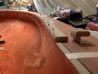
IMG_2205.JPG

As the boat will have a rudder, I used a Dremel to mill out a channel in the gunwales to run control cable tubing. This means I also had to estimate where the seat and foot pegs will be located. As far as I know, the front edge of the seat in solo boats is usually just at or just behind the balance point of the canoe. I went back to the CAD file, found the center of mass of the 3.5" waterline (center of buoyancy) and choose that as the location for the front edge of the seat. The seat will be a pedestal slider with around 16" of travel, so I have some room for error. Then I located the center of the sliding foot pegs 32" in front of the seat. The rudder I choose is the Select Designs Truecourse with gas-pedal type foot controls. The only thing I don't like about it is the weight of the components is heaver than I would have thought. I will likely make replacement parts for it out of carbon fiber in the future, but for now the stock components will do. It seems like a good design.
IMG_2225.JPG

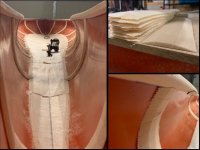
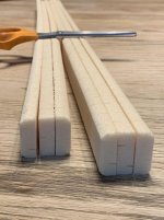
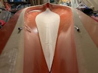
Then I cut some of the sheets for the foam core. These are 1/4" PVC foam (5lb divynicell) that are scored in 40mm squares and attached to a scrim backing cloth. They conform to the curved hull surface, and act as an internal flow media to help the infusion. I tested the scored vs drilled foam, and found that the scored foam infuses better with the rest of my layup, but retains more resin (weight) after infusion. Attempting to calculate the difference, I estimate the total boat weight scored foam will be 9oz heavier than a boat with drilled foam. In my mind that's an acceptable trade-off for a better infusion. I am an amateur after all, and want to make this go as smoothly as possible the first time.
IMG_2229.JPG

I still have to cut out the ribs. I'm not sure how many I need. My 16" test panel had two and was incredibly stiff, so I think I could get away with less, if not any at all. Looking at manufacturer websites for info, the number of ribs varies for ultralight canoes of comparable length: Swift uses 5, Wenonah uses 8, Savage River uses 11, and Mad river uses 5. I'm sure it depends on the layup schedule (which isn't always published). The sides of my Northstar18 (vinylester) is two layers of kevlar and it only has 4 ribs along its length (but each is about 10" wide). I'd appreciate if anyone has insight into this, but I think it is more of a question for finite element analysis software. Almost every part of the hull surface is curved in two compound directions, so there should be a lot of inherent stiffness, and I bet I could get away with no ribs at all. I'll probably do somewhere between 6 and 8 ribs each side.
 
WOW !

I wouldn't class you as an Amateur ! Great planning.

The only thing I'd offer, and you probably already have it figured out.

When I hand laid my 1/8" Cedar inserts, I feathered the edge, so the cloth would lay tight, without any gap at the edge.

I'm not a fan of ribs. If you are NOT going to hang your seats from the Gunnels, I'd skip the ribs !

Once you pull the hull out of the mold, you can access the need for ribs and add as needed.

Reinforcement wouldn't need to go all the way up to the shear, again if you are not hanging seats from the gunnels or hull.

Pedestal seat ??

Jim
 
Looking at your pics closer, I'm wondering about the outwale part of your gunnel foam.
Race boats I've seen ( Flat water) don't have that much beyond the hull.
Seems like they might catch a lot of wind ?
But on the other hand, would shed a lot of water !

Just thinking ! ( again)

Jim
 
Wow, you are fast becoming our Divinycell expert!!
Looking great, can't wait to see the hull out of the mold.

Jim questioned a pedestal seat, have you given it much thought yet? Oops, I see you've already got plans for a sliding, pedestal mounted seat. Any pics or drawings to share? Is this a make or buy arrangement?
 
When I hand laid my 1/8" Cedar inserts, I feathered the edge, so the cloth would lay tight, without any gap at the edge.

Jim

Yep, on my test I chamfered the edges at a 45deg angle. I’d like to go shallower but will have to work out how. My bandsaw table will only tilt to 45. Maybe the answer is a sanding block and some 60grit!
 
Yep, on my test I chamfered the edges at a 45deg angle. I’d like to go shallower but will have to work out how. My bandsaw table will only tilt to 45. Maybe the answer is a sanding block and some 60grit!

Yes, to hand sanding. I used a small plane on my cedar, but that was cedar.

Sanding foam would be effective and easy.

Great progress by the way !

Jim
 
Jim questioned a pedestal seat, have you given it much thought yet? Oops, I see you've already got plans for a sliding, pedestal mounted seat. Any pics or drawings to share? Is this a make or buy arrangement?

Yes, the seat has a build thread of its own. You'll recognize the design as something else Alan came up with. A part of my mold making and infusion practice was making the seat and pedestal. It is meant to leave enough room on the sides to kneel for a bit when my bottom gets sore from sitting all day.

Click image for larger version  Name:	IMG_2238.JPG Views:	1 Size:	368.3 KB ID:	96424Click image for larger version  Name:	IMG_2242.JPG Views:	1 Size:	274.7 KB ID:	96425
 
Last edited:
Nice ! My hats off to you !

I remember your thread. The Seat looks Cool !

Jim
​​​​​​​
 
Ribs are cut and molded from the scrim/scored 1/4" divynicell. First, I located a rib at each mounting point for the foot pegs, then I worked out that I could evenly space remaining ribs fore/aft at about 27" apart. This ended up being a total of 8 each side. My test panel (rib edges chamfered at 45deg) had some slight fabric bridging while under vacuum. To prevent this, I made an extremely shallow chamfer on the rib edges. Each rib is 3.5" wide, and each edge is chamfered at 1.25". I cut them all by hand using a jig I made for the small pull-saw.

Click image for larger version  Name:	IMG_2255.JPG Views:	1 Size:	130.1 KB ID:	96494

You'll notice the rib foam is facing the opposite direction of the floor foam.
The floor is laid with the scoring channels facing out (downward) to aid resin flow to the outer hull fabric layers beneath the floor. Whereas the floor has minimal curvature, the sides where the ribs are have much tighter curves in the tumblehome of the canoe. The rib foam is laid score-channel side facing in: when bent this way the transverse channels partially close down and get smaller. (The ribs aren't critical to resin flow.) If laid the same as the floor, the scored foam would easily conform to the hull curve, but the channels would open up and trap lots of extra resin(weight). So I used a heat gun to make the bends and they laid in nicely.

Click image for larger version  Name:	IMG_2254.JPG Views:	1 Size:	160.4 KB ID:	96495

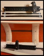
The mounting holes for the foot pegs are on 14.5"centers. The mount instructions call for through-hull bolts, but I plan to infuse T-nuts right into the hull. (i'll pack them with wax to prevent resin filling the threads). There is potential for things to move around slightly during the layup and vacuum bagging, so to make sure the spacing stays correct, I epoxied the T-nuts to a single spread tow of carbon. It is a 20mm wide tow of textreme spread carbon. It needs to be thin and flat to not print through the hull, but just enough to keep the nuts at the perfect 14.5" spacing.
 
Last edited:
Very nicely thought out and executed.

Just my thoughts on foot braces/pegs. Take it for what it's worth.

I much prefer a foot bar/plate that extends the full width rather than pegs mounted to the sides. Legs together is a more powerful and comfortable position when paddling hard and a full width brace gives you a lot of options for foot/leg positions, which can be nice after hours in the seat.

I also prefer a solid brace/foot board with separate rudder controls. This lets you push however you want on the actual brace without affecting the rudder controls, which can be controlled with your toes. It also means you can crank the rudder hard one direction without changing the angle of your foot brace.

In a racing canoe I'd also want the foot brace to be tied in with the seat adjustment so that if I needed to slide my seat on the fly the foot brace would adjust itself. Not only is it a time saver but usually you need to make adjustments because of current or wind directions and that's not always an ideal time to set down the paddling and fiddle with foot pegs in a tippy boat.

Can't believe how fast you're moving!

Alan
 
Thanks! that's good info. I have real limited experience with rudders- and never in a canoe. It's another one of the unknown variables with this project. I know already I don't like the weight of it. I plan to keep it out of the water for straight line/calm paddling and avoid the extra drag. I'll have to get the boat out in some waves and a good beam wind and see how it does with/without rudder. The hull is only 15" wide at my feet so my size 12 dogs will be fairly close together no matter what!
 
I plan to keep it out of the water for straight line/calm paddling and avoid the extra drag.

I predict you'll change your mind once you've got a functional rudder. The ability to take unlimited strokes per side with no corrections or switches is very nice. Far outweighs any drag penalty induced by a rudder.

West Side Boat Shop and many sprint kayaks use a tiller bar. I had one of those and it certainly took some getting used to but once I did I found it wasn't bad at all. I ordered an ONNO foot brace/pedal assy. to replace it as soon as I got the boat because I didn't think I'd like the tiller bar. By the time it arrived I was pretty comfortable with the tiller bar and wouldn't have switched it out if I hadn't already bought the new assy. The nice thing about a tiller bar is that it can stay stationary but still functional no matter where you put the foot brace. It requires feet together paddling though. Just another design option.

Alan
 
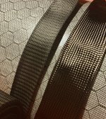
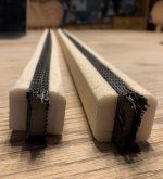
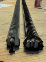
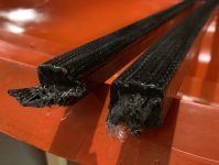
Problem: I had planned on wrapping the gunwales with a carbon/Kevlar braided sleeve. I like the combo of stiff carbon and resilient kevlar. Soller composites will dye the Kevlar for you and I ordered black. I just unwrapped it today and noticed that the kevlar has a distinct shade of green. I attached a picture of the hybrid braid next to an all carbon braid, but I'm not sure it does the color justice: it is much worse in the sunlight. On reading into it, I guess that aramid fiber doesn't take dye very well. I think grey would be fine, but for a boat that is all black and white, I don't think I can live with olive green gunnels. I have a new roll of carbon sleeve coming on Monday.

IMG_2256.jpg
 
I just sandwiched a layer of Carbon between two Kevlar layers.
The carbon shows trough with a green tint.

Lesson learned !

Again, if I'd have done a test ??? I should follow my own advise !

Jim
 
Final mold prep here. On one of my test infusions, the very last part to infuse was the underside fo the gunnel, and there was even a small dry spot. I suspect that this was due to temperature: the bottom of the gunnel was the only place hiding from the infrared tube heater. It was the last part of cloth on the infusion flow path AND the coldest part- both of which contribute to slow flow. So it might be overkill, but I drilled 3mm holes through the gunnels every inch or so to improve epoxy flow here.

Click image for larger version  Name:	IMG_2260.JPG Views:	1 Size:	251.8 KB ID:	96789Click image for larger version  Name:	IMG_2260.JPG Views:	1 Size:	251.8 KB ID:	96789

Next, I polished the mold with aqua-buff 2000 and a wool pad, and cleaned it with the garden hose and some dish soap. I just finished the 5th coat of partall wax tonight, so I'll probably spray PVA and start laying up fabric this weekend.

In between waxings, I infused some thwarts. As with most of this project, I'm not sure how strong these need to be. The largest span behind the seat will be 27" or so. There will be a thwart in front of the paddler, and then carry handles on either end. I cut 1" strips of PVC foam and rounded the edges of the outer pieces to make a rounded box shape. Using the extra carbon/kevlar sleeving I have, I wrapped the central foam strip in a sleeve, then the entire thwart. I then covered it with an all carbon sleeve.

Click image for larger version  Name:	IMG_2260.JPG Views:	1 Size:	251.8 KB ID:	96789Click image for larger version  Name:	IMG_2260.JPG Views:	1 Size:	251.8 KB ID:	96789Click image for larger version  Name:	IMG_2325.JPG Views:	1 Size:	337.0 KB ID:	96790Click image for larger version  Name:	IMG_2260.JPG Views:	1 Size:	251.8 KB ID:	96789

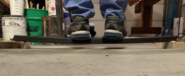
The thwarts were then vacuum bagged and infused with epoxy. Each one is about 36" long, and weighs close to 6 oz. I will cut them to size when the hull is ready. I think they could be built lighter (less layers of sleeving), but I take comfort in how strong they are: they can easily hold my 175# weight standing on the center of the thwart!

Click image for larger version  Name:	IMG_2260.JPG Views:	1 Size:	251.8 KB ID:	96789
 
Last edited:
AWESOME !
I'm guessing we'll be seeing a hull pop out of that mold !

Great work ! I'd say those thwarts are plenty strong !

Thanks again for sharing !

Jim
 
Muddyfeet awesome build!! Can’t wait to see the final product!


Sent from my iPhone using Tapatalk
 
I've been running around like a head with my chicken cut off for the last couple weeks and will be for a while longer yet so I'm not commenting much but am checking in to follow along when I get a chance. I'm impressed. Pretty excited to see the main attraction.

Alan
 
The thwarts look good. I know what you mean about not knowing how strong to make things when you don't really have anything to go on.

On my thwarts I used regular 25psi construction foam and a single 18oz carbon sleeve. That seemed to be stiff enough. I didn't go so far as to stand on it but I did check the flex by supporting the ends and putting quite a bit of body weight on it. Had about the same flex as a wood thwart I checked. But like most things you won't really know until something bad happens to test it in the real world. Mine have a lot of miles but have yet to be tested.

Alan
 
Back
Top