• Happy 1st Sighting of Pacific Ocean by Lewis & Clark (1805)! 🧭

J Winters "Kite" build

I am enjoying this chronology of a build very much. You are really doing a nice job of conveying the nuances of canoe craft. What I like best about boat building is the dream of the tripping that will take place later.

On the tip note, the final layer of the gunnel should be fibre glass tape because you do not want to sand the carbon fibre, and you will be sanding the outer layer because you are an engineer with an eye for detail. (BTW, thanks for posting the cool details of your tests.) Use "frog" tape along with poly to contain the drips and keep a heat gun handy to remove the tape as the epoxy has a habit of hanging on to the edge of the tape.

On a final note, I suppose by now you have come to the conclusion that there is no free lunch when it comes to the weight vs. strength issue concerning canoes. How much weight can you save by making thinner strips? Probably not enough to make it worth while. I could save at the most 10 lbs on my composite canoes, but I am not willing to trip with a boat that might possibly fail while I am out in the wilderness.

LF,
It sounds as if you build in a similar fashion to my style...performance over appearance. What good is a pretty boat that can't be used (or abused)? I built my 16'8" DY Special at 31 lbs...but that was using butt edged strips. I guess I must have sanded much more than I could measure. Near the sheer, I measured the substrate thickness and there was little loss. Around the bilge is impractical to measure, and that's likely where the disparity in material removal lies. As to weight savings, this hull has about .938 cu ft of cedar, at 22 lb/cu ft, that's over 20 lbs in cedar alone! Even a 1/32 thinner strip would yield nearly a 17% weight saving (all before sanding)...every 3 lb helps.
Do you have any photos to share of your gunnel construction? I'd surely like to see what you've done.

I'm surprised one layer of CF doesn't give enough stiffness (being so strong in tension). To me that seems to indicate that something is failing in the core, maybe the foam is not good enough in shear and the full loads are not being transferred to the CF. If the core isn't the problem, I'd think making the section more "T" (wider) shape would get your moment of inertia up and be a better trade.

If it is a problem with the core, I'd consider using an extra cedar strip prependicular to the shear and add a little foam under it to form it into a gunnel shape. Then CF over the whole thing. The cedar strip would be better to handle the shear stresses and the CF takes the tensile loads.

David

David,
I think the single layer of CF is just too thin, I need more section to take advantage of the high tensile strength. Ultimately, the foam substrate should act only as a form, it's modulus is so far below that of the CF composite as to be insignificant... but I'm not a composites guy, my world is mostly super alloys, rotordynamics, and tribology. I do like your idea of a T section, integrating some cedar. I was thinking that the CF and foam work would be play time, I guess I have to earn my wings. I don't have a back up plan should I not be able to get the CF to work for me, so I suppose I have to do my homework.
 
It sounds as if you build in a similar fashion to my style...performance over appearance. What good is a pretty boat that can't be used (or abused)? I built my 16'8" DY Special at 31 lbs...but that was using butt edged strips. I guess I must have sanded much more than I could measure. Near the sheer, I measured the substrate thickness and there was little loss. Around the bilge is impractical to measure, and that's likely where the disparity in material removal lies. As to weight savings, this hull has about .938 cu ft of cedar, at 22 lb/cu ft, that's over 20 lbs in cedar alone! Even a 1/32 thinner strip would yield nearly a 17% weight saving (all before sanding)...every 3 lb helps.
Do you have any photos to share of your gunnel construction? I'd surely like to see what you've done.

31 lbs for a 16' 8" DY is sweet!

Here are some pics. These 2 are of my first attempt of a kevlar build. The exterior of the hull looks rough because my fancy kevlar "scissors" I paid the big bucks for failed after the first cut. The epoxy was setting up so we folded the kevlar over on itself. It is funny now after hundreds of miles have been put on her. This canoe has been lashed to planes and trucks and bashed into rocks on the trail. Sorry I don't have any pics of the process after the styrofoam, but that is probably because of all of the time spent trying to keep the frayed ends and strands of carbon fibre on the gunnels. This canoe has 3 layers of carbon and one layer of 6" fibreglass tape on the gunnels and it is super strong. However, the ends can only take so many bashes into rocks on portages before it needs a repair.DSC_0022 - 2011-04-04 at 20-24-08.jpg DSC_0030 - 2011-04-04 at 21-00-36.jpg

These pics are of the solo canoe. When I did these gunnels I used 3 tables covered in wax paper to wet out the fabric layers before putting them on the styrofoam. I pre cut 3" strips of carbon fibre and wetted them out on top of a 4" strip of kevlar tape. I did this to keep wayward strands of fabric hidden under the kevlar tape. I should have used 5" tape, live and learn... When this was all wetted out I put it on the gunnels and pressed it down until it set up and stuck. then I put a 6" strip of fibre glass tape on the surface of all of that. I am not recommending this procedure, it is just how I did it. It worked.

DSC_0002 - 2013-08-30 at 11-09-56.jpgDSC_0020 - 2013-08-30 at 18-47-45.jpg

As you can see my seat is on the bottom of the canoe and I sit on comfy kevlar. Best seat material there is. The custom yolk rests inside the canoe attached with velcro and attaches to the gunnels, also with velcro. The seat is attached to the canoe with velcro also. It is situated 7" off the very bottom of the canoe and its' centre is 6" back of the centre of the canoe. The seat is not in the way for portaging.
It works for me, in fact so well that I will never go back to the old ways.
 
LF,

Thanks for the photos, I can tell a lot just from looking at them.
I just bought some 4" fiberglass tape, to put under the CF tape...it was only $26 for 50 yds!! Cheap insurance.
I showed my sample gunnel section to my SIL this evening. He was surprised that the section was as stiff as it was, and mentioned that his CF parts take a few days to develop their full strength.
And I plan to do a half wrap spiral on the thwarts and seat frame, so all of those parts will have a double layer of CF tape.
So I wait until the glass tape arrives. In the mean time, I have decks and bulkheads to build, and some more sanding on the hull.

I like your portage yoke, I had one very similar that I made in cedar...it's now 30 years old!!
 
I think the foam does a lot more than provide a form, for it to be effective it has to have sheer strength. If it deforms at all, it won't transfer much of the loads out to the vertical section of the CF. If you made the gunnel from a stack of unglued verticle laminations wrapped in CF you'd get the same thing as a weak foam. Almost all of the resistance to side deflection would come from the horizontal part of the CF wrap. By adding the 3 layers of CF and Fiberglass you're effectively creating the "T" I mentioned in my previous post so some of the stresses can be distributed further from the neutral axis.

I really need to draw some pictures to clarify what I'm thinking. Maybe even do some math to back it up (if I remember how).

BTW, I'm just hypothisizing, I might be completely wrong.
 
Well,
I have my sample gunnel section here at work. I am quite surprised at how stiff the CF and foam has become, now that it has cured for a bit.
I should have time later today (lunchtime) to cut the sample section into a baseline test beam and a gunnel test beam. The composite modulus for me is a mystery...but, I can readily determine the flexural rigidity, EI, if nor definitively, then at least comparatively. I'll keep the baseline substrates equal as much as possible, so the only difference is the added gunnel section.
I'll be sure to document with photos and test data for those that are still hanging around, sorry if this is glazing some eyes, but this type of design data is fascinating for me.

Dave,
If you can develop some closed form solutions, I'd love to see them, but don't stick me with a 4th order differential equation, I pass those on o the PhD's that work for me!!
 
I'm glad you can do the testing, I trust that more than any calcs I can do! Don't worry no diff eqs from me..I'm thinking simplify the cross section to a square or rectangular shape and calc. the moment of inertia and the max shear at the CF/foam interface. What are your gunnel dimensions?

I'm curious how you are going to load the CF gunnel and not damage it by essentially creating a point load. I'd be worried that you cause the failure by the loading technique and not push the material properties. Seems like you need a long simply supported gunnel to get the point loads down as low as possible.
 
Dave et al,

I do have a long section and applied a localized load. It's too difficult to post anything from work, but I do have numbers and photos of the set up.
Just for a tease, I'll tell you that my baseline hull section was 2" wide, and the flexural modulus was about 450 lb-in*2, and the CF gunnel section was 1400 lb-in*2...
 
Here's the complete story, now that I can easily post the photos...

I used a leftover deck from my nephew's build (finished in 2013), and used some Cabosil thickened epoxy to stick the foam on an edge. I then wrapped the CF bias woven tape around the foam, and wet out the CF. I had barely any resin left in the tray, so I may have starved the CF.

This is what I started with

DSC_1150%2520%25282%2529.JPG


I cut the deck piece into two 2" wide strips, one just the previously laminated deck, the other side with the foam and CF tape. I kept the wood and glassed parts the same 2" width, so any differences in strength and/or stiffness could be attributed to the gunnel section only.

DSC_1151%2520%25282%2529.JPG


Here's how they looked from the end...that's a Starrett 12" rule in the photo, just for a reference.

DSC_1152%2520%25282%2529.JPG


Then I put the baseline section (glass/cedar/glass only) in a little load frame. I operated in load control and used a 10 lb setpoint. Here is the baseline section at about the max load.

DSC_1154%2520%25282%2529.JPG


After doing the baseline load-deflection test, I put the sample gunnel section in the load frame and repeated the test. It was quickly apparent that I needed more than 10 lb load, so I increased the setpoint to 25 lb. Here is the CF and foam gunnel at the max load. Look carefully and you'll see a laminate failure on the compression side. I attribute that to my negligence, or maybe laziness when I didn't use enough resin the wet out the CF properly. (hint, the failure is about an inch to the left of the applied load)

DSC_1157.JPG


And here's a comparative plot of the baseline hull section and the CF gunnel section.


Gunnel%2520Plot.JPG


If anyone wants to verify my numbers, here they are. The distance between the supports was 11 15/16 inch, max loads were 10 and 25 lbs, for the baseline and CF gunnel respectively. Deflections were 0.773 inch and 0.628 inch. Interestingly, the baseline section had no hysteresis, the CF, with the compressive failure, had a huge hysteresis loop!!
And here are the details on the baseline substrate...cedar was .12 thick with single layer 4 oz cloth on each side, for a total thickness of .13 inch. Width and length was 2.0 x 14 inch. Foam substrate was 0.75 x 0.75, with a 0.25 radius 2x, and a 0.13 x 0.50 groove. Baseline weight was 0.085 lb and gunnel section was 0.155 lb.


What does all this mean?? How do I know?? OK, maybe I know...From these first indications, that single layer of CF over the foam could be sufficient, assuming:
1. There is a complete bond between foam and hull in the groove.
2. There is solid contact between the CF tape and the foam and hull.
3. The CF tape is fully saturated.

Now, I did order some 4" glass tape, I'm a belt and suspenders sort of guy.
I am pleased though, with the look of the CF tape...it will be very easy to keep a clean, straight line, and resin drips should not be an issue. The black CF tape contrasts nicely with the cedar, and I expect it will look even better against the red pigmented resin.

Well, guys, what say you??
 
Looks good. Get'er done SG.

PS If you get it together and it's not stiff enough to suit you you could probably add another layer of CF.
 
Last edited:
" What does all this mean?? How do I know?? OK, maybe I know...From these first indications, that single layer of CF over the foam could be sufficient, assuming:
1. There is a complete bond between foam and hull in the groove.
2. There is solid contact between the CF tape and the foam and hull.
3. The CF tape is fully saturated.

Now, I did order some 4" glass tape, I'm a belt and suspenders sort of guy.
I am pleased though, with the look of the CF tape...it will be very easy to keep a clean, straight line, and resin drips should not be an issue. The black CF tape contrasts nicely with the cedar, and I expect it will look even better against the red pigmented resin.

Well, guys, what say you??[/QUOTE] "

Stripperguy, Interesting stuff.

After thinking about my previous comments, I realized that my Kevlar canoe doesn't have the inherent rigidity of the cedar strips with glass on both sides that the cedar strip canoes have prior to the gunnels. The kevlar is quite floppy before the gunnels. So this means that your canoe does not need the 3 layers of CF for lateral rigidity. However, try this real world test on the sample piece. Take a hammer or a piece of wood or something and hit it from the top to test what it takes to shatter the CF, because that is the problem with CF. When it fails, it is gone, shattered, done. The hazard is the wind catching that beautiful canoe and swinging the gunnel into a rock, or sharp blunt end of a broken branch and smashing the CF.

The glass tape is clear so you will not even notice it. One wet-out of the CF will not be suffecient. That is where the glass tape comes in. If that was my boat I would CF, glass tape, light sand and final coat. Minimum, maybe 2 light sands and 2 coats, thin coats. The bond with the styrofoam is not an issue. It will bond, but really the foam is not much more than a spacer.

Of course I noticed that the cedar strips on your test piece are at an angle, no perpendicular to the gunnel like your real world canoe will be. Did this have anything to do with the failed area? Probably not since it was on the inside, but just wondering.

You will get drips from the epoxy. If you can pull the gunnel project off with no drips, let me know your secret because I have epoxy all over my clothes, the floor and down the side of my first canoe thinking it wouldn't run that much.
 
Seeing the buckling failure I think you might get better performance putting the foam on the inside of the gunnels. This would move the neutral axis inside the gunnel so the cedar strip could be used for the compression loads and the CF would take the tensile loads.

This assumes that the loads are in towards the center of the boat, I'm not sure this is a good assumption.
 
Looks good. Get'er done SG.

PS If you get it together and it's not stiff enough to suit you you could probably add another layer of CF.

Rippy, Are you still watching? I'm trying not to be too technical, but this sort of data fascinates me. This particular CF tape cost me nearly $150, and the rest of the boat was only $500. I can't justify any more luxurious expenditures like this. Not that I can't afford it, it's just not practical! See the next response below.
And since this boat is going to be heavier than I had hoped, maybe I can trade you for one of your knives.;)

" What does all this mean?? How do I know?? OK, maybe I know...From these first indications, that single layer of CF over the foam could be sufficient, assuming:
1. There is a complete bond between foam and hull in the groove.
2. There is solid contact between the CF tape and the foam and hull.
3. The CF tape is fully saturated.

Now, I did order some 4" glass tape, I'm a belt and suspenders sort of guy.
I am pleased though, with the look of the CF tape...it will be very easy to keep a clean, straight line, and resin drips should not be an issue. The black CF tape contrasts nicely with the cedar, and I expect it will look even better against the red pigmented resin.

Well, guys, what say you??
Stripperguy, Interesting stuff.

After thinking about my previous comments, I realized that my Kevlar canoe doesn't have the inherent rigidity of the cedar strips with glass on both sides that the cedar strip canoes have prior to the gunnels. The kevlar is quite floppy before the gunnels. So this means that your canoe does not need the 3 layers of CF for lateral rigidity. However, try this real world test on the sample piece. Take a hammer or a piece of wood or something and hit it from the top to test what it takes to shatter the CF, because that is the problem with CF. When it fails, it is gone, shattered, done. The hazard is the wind catching that beautiful canoe and swinging the gunnel into a rock, or sharp blunt end of a broken branch and smashing the CF.

The glass tape is clear so you will not even notice it. One wet-out of the CF will not be suffecient. That is where the glass tape comes in. If that was my boat I would CF, glass tape, light sand and final coat. Minimum, maybe 2 light sands and 2 coats, thin coats. The bond with the styrofoam is not an issue. It will bond, but really the foam is not much more than a spacer.

Of course I noticed that the cedar strips on your test piece are at an angle, no perpendicular to the gunnel like your real world canoe will be. Did this have anything to do with the failed area? Probably not since it was on the inside, but just wondering.

You will get drips from the epoxy. If you can pull the gunnel project off with no drips, let me know your secret because I have epoxy all over my clothes, the floor and down the side of my first canoe thinking it wouldn't run that much.

I did buy some 4" glass tape, and I'll use it if I have to, but I'm trying my darndest to keep the weight down. And I'm still thinking how to properly simulate an impact test as you describe, maybe some sort of modified charpy test.
I actually did have one of my hulls tossed by the wind, in 2002, October, on Indian Lake, ened up with an above the waterline rupture in the hull. I generally abuse my boats below the waterline. The gunnels need only hold the boat on the roof racks and transfer the loads from the hull to the thwarts. I know from my research background that CF is terrible in abrasion resistance, much like a pencil, so I can see the benefit of a glass covering layer.
Yeah, the cedar strips are at an angle, that was a leftover laminate, I wanted to maximize my data/effort quotient.
And I was concerned about runny resin, but a line of tape as a mask should be all I need to avoid the runs. If you could inspect my test piece in person, rather than via a low res photo link, you'd see that there is little excess resin on the substrate...I've been doing this for a while now, since 1978!!
I just haven'y had any experience with the CF over foam build ups.
After this bit of messing around, I think I'll get more serious about a skin on CF/foam frame hull. I've been toying with the idea of a guideboat, built as a SOF, for a while, not willing to commit due to my lack of experience. But now...
 
Seeing the buckling failure I think you might get better performance putting the foam on the inside of the gunnels. This would move the neutral axis inside the gunnel so the cedar strip could be used for the compression loads and the CF would take the tensile loads.

This assumes that the loads are in towards the center of the boat, I'm not sure this is a good assumption.

Dave,
I'm certain that the buckling failure was my fault due to inadequate wet out. It should have failed at the max deflection location if it was a true laminate failure.
And just which way are the loads realized on the hull/gunnels/thwarts?? And does it even matter? I suppose I should compare the strength of my usual mahogany gunnels, they hold up for decades without any yielding...
 
Ya, I'm still along for the ride. I'm interested in seeing the fitting out of the seat, gunnels and such.
 
Update without photos (sorry guys, nothing exciting yet)
Tuesday night I wore out my fingertips sanding that crease. Tonight I put a skim coat of red pigmented resin on that very same crease, it looks pretty good.
Also put a seal coat on the other side of the stripped panel that will become the bulkheads and decks.
And that's about all, soon will be cutting and fitting the decks and bulkheads, trim the sheer line, CF over foam trim.
 
I'm reluctant to post any updates, after seeing Conk's workmanship...

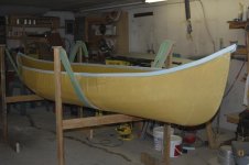
Here's the Kite with a fresh skim coat on that creased tumblehome, any irregularities will sand out soon.

DSC_1446.JPG


I ran into my first snag today...the panel that I stripped, sanded, sealed and glassed is too small for my intended decks and bulkheads. I missed by this () much!!
Since I refuse to strip another panel, I decided to make the aft deck and bulkhead a little smaller. But, now the bulkhead would fall between forms 13 and 14. So what, you say?? Hmmm, I usually use a form for the template for the bulkheads, now I had to make a template by trial and error for the aft bulkhead. After many cuts on some luan plywood scrap, I finally had a decent template.

DSC_1448.JPG


Confident once more, that I can fit all the parts on my stripped panel, I prepared to bandsaw cut the aft bulkhead...but wait!! What's this?


DSC_1447.JPG


Yup...I was teaching one of the guys at work how to weld a bandsaw blade. I welded a 1/4" wide 14 pitch to demonstrate the method...this 1/2" wide 4 pitch was a few inches too short for my saw at home. He watched me weld the other blade, and then followed my lead exactly to stretch this blade a few inches. Well, not quite the way I would have done it!!

After sawapping in another blade, I cut the bulkheads and decks to fit at each end.

DSC_1451.JPG


DSC_1452.JPG


Then I taped the bulkheads in place, mixed some Cabosil thickened resin, and epoxied the bulkheads in place from the inside.

DSC_1458.JPG


DSC_1454.JPG


DSC_1460.JPG


Once those epoxy fillets cure, I'll do another fillet on the outside of the bulkheads, and tab in the bulkheads with some bias cut glass.
I'm getting there, but still a ways to go.
 
I guess it's time for an update...I wait still for the balance of my CF tape order to come in, so no trim work yet. I did abuse that sample section of gunnel that I tested at work, I bashed it a minimum of 10 times about as hard as I would drive a 10d nail (does anyone hammer nails any more??) and there was no delamination, no softening of the laminate, I'm think I'm good to go.

Now, for the boat itself. I epoxied the decks on after the cleats to hold them were stuck on. It's been 3 days and the resin is still a tad soft...I was getting worried, but the leftovers kicked just fine once in the house, I just need a few warm days.
While waiting for those decks (and still waiting for the CF tape) I again wet sanded that crease, for the very last time, I swore to myself!
Also trimmed the sheer line. I thought I liked the lines of the boat before, but now, whew!!
Here's a few looks at the hull with the sheer trimmed, try to look past all the wet sanding residue.

DSC_1464.JPG


DSC_1465.JPG


If you're looking closely, you've noticed that the stems are still a bit high, yeah, I have to sand them down a little more yet.
I particularly like this view...

DSC_1466.JPG


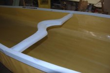
And here you can see how the blunt stems, decks and bulkheads help to define the shape. Once the black CF gunnels are on, it will really pop!!

DSC_1468.JPG


And last photo for tonight, I promise. I keep trying to get a good image of how smooth the hull is, I don't think the photos show it properly. I wet down the crease to clean up the wet sanding residue, there's some water dripping in this photo. The crease itself is very uniform and smooth. You can see that the resin is still barely translucent, I kind of like it that way. From any distance, it looks solid red, but as you get closer, you can start to see the wood grain and color variation.

DSC_1472.JPG
 
Epoxy on decks has finally firmed up, so I glassed in the bulkheads and decks.
Here's the stern, with some bias cut strips of leftover 4 oz cloth, just itching to be wet out.

DSC_1473.JPG


Here's the bow, same story, the glass is tucked in very well under the crease, and in some spots, up and over the sheer.

DSC_1475.JPG


Here's a close up view of the bow seams, before wetting out.

DSC_1476.JPG


And here's the stern all wet out...

DSC_1478.JPG


And finished bow. All of this was wet out with a natural bristle brush, too difficult to reach with a roller or squeegee.

DSC_1481.JPG


And that's about it for now. Still waiting for the rest of my CF tape to arrive.
So let's see, gunnels, thwarts, seat frame, that's all that's left to finish...Oh, and the clear coat on the outside.
I'm wavering on my seat attachment method. I'll still use velcro to position and attach the seat frame, but to what?
Should I glass in some cleats? That would require a seat frame that's nearly 24 inches wide.
Or maybe I should make some sort of pedestal, to support the seat frame from the bottom of the boat?
I guess I better make some sketches...
 
I know this is my thread...but I'm the only one posting. I hope I'm not overposting!! Is anyone still watching? I can't trust the counter.

Real quick...finally finished all the wet sanding, cleaned and rinsed the hull, made a couple of thwarts.

DSC_1500.JPG


DSC_1504.JPG


DSC_1505.JPG


DSC_1507.JPG


DSC_1510.JPG


I am getting anxious to see how this hull will handle white and big water. I have no doubt it will be a pleasure on little twisty streams.
 
Back
Top