• Happy Birthday, Ansel Adams (1902-84)! 📷🌄

Solo on the Light Side

Joined
Jul 18, 2016
Messages
1,098
Reaction score
801
Location
Bowmanville, Ontario
Solo on the Light Side

Over the past couple of months, I noticed something about the canoe lookingfor/purchase/release threads that I never noticed before. There is a repeating theme of wanting to tweak and change some things, wishing for others in various boats, as they get discussed.
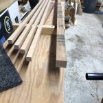
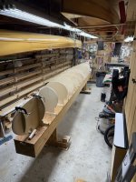
It dawned on me that this is why builders collect so many boats ... when they get an idea or want to try that or see something that's cool, the internal response is ... I could build that ... that is the how and why the DIY rabbit hole gets so deep so fast.
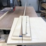
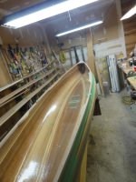
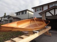
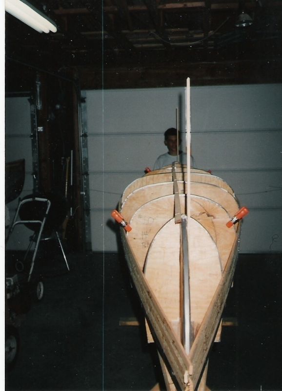
In 2019 I took the lines from a 14' KeeWaydin and stretched it to 15', modified the bow/stern a little and made a fairly light solo canoe. The canoe very closely fits my needs, except when I get near the shoulder seasons, then the warmer gear makes the bags a little larger and the canoe just a little crowded. Although I am pretty sure I am mid range in the load capacity, I would like to be closer to the lower end so the boat has a little less draft.

Discussing the idea of extending the length to 17' with some of my camping friends, it was pretty much figured that moving from 15' to 16' would be optimum, the little voice in my head wasn't really convinced, so 17' will be the new build. To keep it interesting, the challenge, for me, is to build the new canoe at or less than the weight of the 15' version.

The original is about 31 pounds at 15' or ~2 pounds per foot, which means I need to figure a way to be 4 pounds better than last time, with out compromising the overall strength. Over the past 18 months I have been reprocessing strips, acquiring materials and researching alternative ways (for me) of building and figuring out how to achieve that 4 pound reduction goal.

The basic planned changes (there will be tweaks along the way) and the expected impact for this build are:

- swap from 6 oz E Glass to 4 oz S Glass, ~ 1.5 pounds
- using an epoxy pre seal coat, ~ .75 pounds
- lighter version of foot braces, ~ .5 pounds
- balsa/fiberglass thwarts, ~ .5 pounds
- stemless construction, ~ 5 oz

The build is about 2 months along and as with the last build thread, I will be breaking this one down into sections, less attention to repeated items from last build (things I didn't change) and more on things that are new to me. The glassing has the biggest changes and rationale will be covered when I get to that section.

Should be a fun ride.


Brian


Last build link for those interested:

 
Yes ! It's This time of year, when we start dreaming up a new build !

Two things, in the weigh savings. A Kevlar copy , with Aluminum gunnels, notice I didn't say cost !

Kevlar will likely double your weight reduction.

Second, a stemless build, will likely reduce the weight by more than .5 #, I'd say double that.
And then the time saved, constructing and fitting stems, is a big plus.

A note on thinning strips, though you didn't mention it, I took my 1/4" ( .25") strips, down to .22".
I'm sure I could have taken them down more, but I'm sticking with a 1/8" R. (1/4") Bead and cove bits.
They worked fine on my last build.
I did purchase 3/32"R bits, as described by Nick Schade, in one of his builds. I would need to thin my strips even more, to get them to work.

Now contemplate 1/8" thick strips. I would think this is doable, I just haven't had the guts to try them. Maybe I'll just cut a few, and see if they would work.

Nice to hear you are starting another build !

Last thing I will bring up for now, is Stretching a design.
I was always told to adjust the width accordingly, to maintain similar handling characteristics.
A print shop has done that, on several for me.
Just a thought !

Good Luck !

Jim
 
Two things, in the weigh savings. A Kevlar copy , with Aluminum gunnels, notice I didn't say cost !
I will say it COST

Second, a stemless build, will likely reduce the weight by more than .5 #, I'd say double that.
And then the time saved, constructing and fitting stems, is a big plus.

I have long held the belief that stemless wasn't a big weight saver .... I made the model, it really just doesn't produce the kind of weight savings you might think, in this build I think 5 oz is pretty close to correct answer. The weight of the inner and outer carved stems just isn't that high, then you subtract the weight of the strip area that replaces the stems and ... well .... ~5 oz difference

The first post will cover strips ... I am taking incremental steps and building on stuff I learn and that I know works, adding new stuff to see how that works ... the new strips are 3/16" and I also bought a set of 3/32" radius B&C bits.

I was always told to adjust the width accordingly, to maintain similar handling characteristics.

Totally correct and I figure doing it without that step may be a bit "sketcky" .... on the flip side I am not really trying to just make it bigger, the longer length is also a performance gamble. I am mostly on lakes and the occasional twisty, turny stream ... so the hope is while I may lose some maneuverability in favour of "on-the-lake" performance.
That's the exciting part, this entire boat design has been gambling from the start, hopefully the roll holds.

I made need that luck Jim, thanks
 
Strip Prep - taking place late fall 2023

Sorted through all of my left over strips and strip lumber, figure I have enough on hand for this project, so bonus, I don't have to buy strip lumber.

The lesson learned from the previous build of this hull was that strips need to be narrower and flexible so they are going to be 3/16" x 5/8" , there is a lot of curving on this hull and the narrower strips will follow the shape better and easier, although I will have to use a few more strips (I can live with that).

I pulled all of my WRC out to see what was useful for this build. They are 1/4" x 3/4", so will have 1/32" planed off each long side, followed by trimming 1/32" off of each edge. Then they get bundled and put away for now.

IMG_3598.JPG

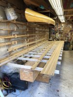
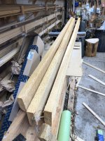
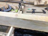
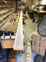
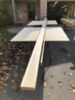
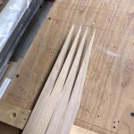
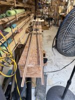
I also have (3) 8' x 2" x 6" NWC boards in the shed that will supply the longer strips for this build. The 3 boards will be skarfed together, to make a single board 19' long. I will point out that this is a decision point ... you can make a bunch of 8' strips and then eventually butt joint them on the boat or make these 2 bigger joints and make full size strips. My choice was to do 2 bigger joints now and not do north of 200 smaller joints on the boat later.

IMG_4422.JPG

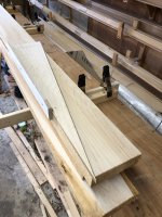
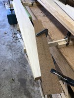
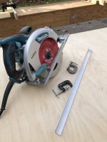
I give these a very light plane, just to get then all the same thickness, but taking the minimum off. Made up this jig to both mark and guide the circular saw to cut the appropriate angle

IMG_4429.JPG

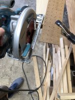
Cutting an angle looks like this

IMG_4433.JPG

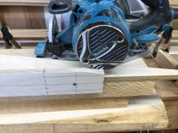
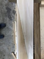
Since the jig isn't reversible, the other angle cuts on the line like this

IMG_4435.JPG

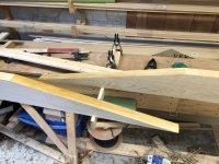
IMG_4436.JPG

The cuts are lightly sanded with a block and 100 grit sand paper to remove any polishing the saw made during the cut. Each joint to be made is dry fit and alignment marks are added.

IMG_4459.JPG

Glue up is:
1) saturate cuts with unthickened epoxy

IMG_4439.JPG

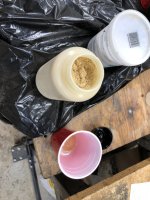
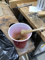
2) thicken a batch of epoxy with cedar dust and cabosil, to the consistency of peanut butter

IMG_4440.JPG

IMG_4443.JPG

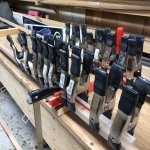
3) apply the thickened epoxy to cuts and clampup. I didn't take photos of this clamp up, but the process is pretty well standard for my builds, if you want to see how I handle , you can look here : https://www.canoetripping.net/threads/freedom-solo-16.73582/post-73613

IMG_4446.JPG

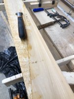
4) use a scraper to "carefully" remove the excess hardened epoxy and cleanup a little with 100 grit sand paper on a block. The cedar is soft, don't get aggressive with cleaning up or you will tear hunks out of the wood, also cleanup is to just get things sort of flat and straight again ... it's all getting cut up so DON'T waste your time making it pretty at this step

IMG_4466.JPG

IMG_4468.JPG

and the result

IMG_4472.JPG

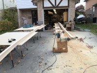
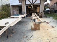
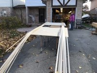
Now we haul the strongback out onto the drive way, set it up to rip strips and prepare to annoy the neighbours for a few hours

IMG_4487.JPG

Making strips with a circular saw is a pretty simple, low tech affair ... you can find a more detailed description here : https://www.canoetripping.net/threads/skilsaw-method-for-strip-cutting-a-primer.123822/

IMG_4481.JPG

The 19' board ready to be sliced up, you can see the skarf joints better in this shot.

IMG_4479.JPG

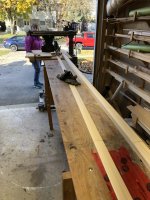
And the stack of 3/16" x 2" strips are all stacked, took about an hour ... will take a bit to cleanup the drive though and reset equipment to cut the 2" strips to the width of 5/8". The rough strip is just a tad over 2" and I changed up from a 10" blade to a 7 1/4" thin kerf blade (radial arm saw), so I can get 3 strips from each wider strip and they are just a small bit less than 5/8". Two passes will be required through the saw, with a setup change at each pass.

IMG_4487.JPG

Saw infeed table

IMG_4491.JPG

saw cutting and hold down setup

IMG_4492.JPG

Outfeed table with finished strips on the left and double width on the right. After setup adjustment, the double width produce 2 finished strips ... so each 2" strip yields 3 finished strips at 5/8"

IMG_4493.JPG

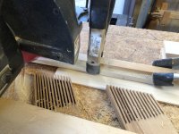
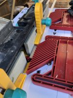
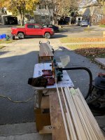
Working in a small space means I have to reconfigure for each operation, so now the saw is put away, infeed and outfeed tables are added and the router is wheeled into position and setup to cut first the bead, then the cove on each strip. Additionally, those resized WRC strips are retrieved and they will now get a new B&C.


Router setup is pretty straight forward, hold strip before and after, finger boards at cutter head

IMG_4495.JPG

and strongback as infeed table and the outfeed table

IMG_4496.JPG

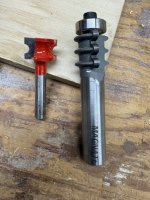
The last build used a 1/4" B&C set on 3/16" strips and they worked reasonably well. There were issues with wider strips (7/8") being a a little unruly in curves and the B&C tended to pop out of track ... so this build I have reduced strip width to 5/8" and went with a 3/16" B&C set, hopefully resolving those issues.

To get said B&C is a little tricky, Frued makes the bead cutter, but I had to get a fancy 3 head flute cutter to do the cove cut

IMG_6502.jpg

All the strips are bundled and put in the racks for storage .... in the fall of 2023, life happens, just getting started now in 2025
 
Stem Revisions

Bit of a foreword, this build is transitioning from a stemmed to stemless build and a length from 15' to 17' and that will require some changes to the stem molds.

Moving to the stemless technique is expected to yield ~6 oz weight reduction, you can check the rationale at the end of the post if you have any interest. The main reason for trying the stemless method is very simple, 1) I haven't tried it yet and 2) I like the idea of a sharper entry profile .... the 6 oz or so weight savings is also welcome.

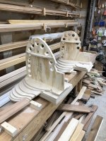
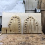
Most of the forms can simply be re used when extending the canoes length ..... except the stern/bow assemblies, this is the pile of forms from the previous build

IMG_1511.JPG

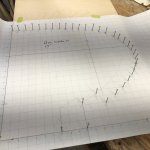
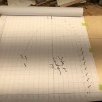
To lengthen this canoe, we are stretching the spacing between the forms, there are 2 forms attached to the bow/stern assemblies and to keep it all proportional, i need to redraft the actual stern/bow forms, There will be 2 things being done during this re draft 1) stretching the form and 2) adding back the material the inner stem used to occupy (we are going from a stemmed to stemless form)

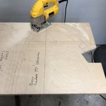
the new bow section being transferred to plywood

IMG_6190.JPG

the new stern section being transferred to plywood

IMG_6192.JPG

and a comparison of the old to new forms

IMG_6194.JPG

These are cut out with a jig saw, staying about 1/16" outside the lines so that the shape lines aren't destroyed

IMG_6197.JPG

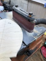
then the forms are sanded down to the exact line (this is a recycled pic for sanding forms, from previous build)

IMG_1413.JPG

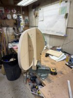
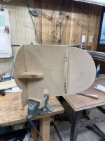
The bow/stern forms have centerlines, waterlines and mounting lines re established on the new forms and the assemblies are then put back together. You can also see the lines drawn for shaping the form edges around the perimeter where the stem would go, these are setting up the 1/4" center area that doesn't get shaped away.

IMG_6272.jpg

the assemblies do require re enforcement to keep the forms square to each other

IMG_6275.jpg

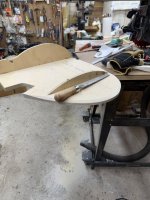
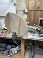
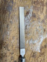
The first small snag I ran into was carving/shaping the edges of the stem forms ... when you use stems they are typically cedar and are a snap to shape, this is Baltic Birch Ply and hardwood is a little more resistant to removal. I have several rasps including a Shinto and none of them were very effective, so good excuse for a new tool, I ordered 2 "Japanese Milled-Tooth File" from Lee Valley, to try .... they worked awesome

shaping in progress

IMG_6288.jpg

final assembly

IMG_6297.jpg

Link for the file


and this is what they look like

IMG_6299.jpg

Another item off the prep list done


And for those with any interest, might as well do the "weight discussion" here as well.

No one here would believe that a stemmed build is lighter than a stemless build, everyone (including me) would likely believe the reverse to be true. Here's the rub with that statement, without some idea of the actual numbers, it's hard to determine if the difference is significant. For example Car A gets 20 MPG and Car B gets 20.2 MPG, Car B has better mileage, but does it really matter enough to be part of the decsion making process?

The measurements here are based on the current build, the stem areas are broken into 2 pieces, the bilge chunk and the more vertical Roundy chunk
Total Length : 36"
Bilge Part : 12"
Roundy Part : 24"
Width : .75"
Depth/Thick : .75"
I normally use Cherry outer and NWC inners, so I will use those in this example
Cherry Density : 39 lb/Ft^3 or .3611 oz/In^3
NWC Density : 22 lb/Ft^3 0r .2037 oz/In^3

INNER Stem
The Inner stem is the easy part to figure, it doesn't exist in the stemless build, so whatever it weighs is 100% weight reduction.

The whole inner stem in NWC weighs L x W x D x Dnwc ..... 36 x .75 x .75 x .2037 = 4.125 oz

However, a lot of that gets carved away, so if we allow 50% on the roundy bits and 20 % on the bilge part, that weight drops to ~1.65 oz


OUTER Stem
This one is a little trickier to present, as it isn't just a matter of removing the stem. if you assume that the stemmed and stemless builds have the same finished shape, it follows that if you remove the outer stem, the empty spot you create will need to be filled in the stemless build, so replace cherry with cedar. So basically, each strip extends a little further in a stemless build to cover the space where the stem would be on a stemmed build.

Again breaking the stem into two basic pieces, the roundy bit will be Volume 1, it is 24" long and about 50% will be carved away, so Volume 1 will be 24" x .75" x .75" x 50% = 6.75 in^3
The Bilge part is Volume 2 is a little more difficult, because it basically fills a slot you cut in the bilge strips. It is a wedge shape .75 at turn, going to .25" at end and is about 1/4" thick ... so Volume 2 is (.75 + .25)/2 * .25 * 12 = 1.125 in^3

When you consider the stem area this way, the volumes allow you to estimate the weight of each style of building

So the weight of the cherry outer stem would be ( Volume1 + Volume2) * Cherry Density .... (6.75 + 1.125) * .3611 = 2.84 oz

There is always a wrinkle in comparing like this, fortunately, this is a small one that can be calculated pretty easy. When you use a stemless build, there is an air triangle created where the strips pass the stem form ... to be fair, this volume needs to be subtracted from cedar side of the comparison. In this case, it is .25" base and a .5" height, applied over the roundy bit will yield a volume of 1.5 in^3 and will be designated as Volume 3

So the weight of the cedar occupying the outer stem volume would be (Volume 1 + Volume 2 - Volume3) * .203704 = 1.30 oz


Estimate of Impact

Losing the inner gunnels reduces weight by ~ 1.65 oz/stem, saving on Outer stem volume reduces weight by ~ 1.55 oz for a total of 3.2 oz per/stem or ~ 6.4 oz for both stems


Granted this is not detailed model, but I think it is a reasonable estimate of the actual weight impact that the two methods bring to the table.
 
I'll grant you, that there is not much weight reduction going to a stemless build.
The time it takes to shape a stemless form, should be about the same as shaping the inner stem.
A stemless build doesn't require steam bending, or laminating both the inner and out stems. Both time, energy, and material costs.
If your outer stem is made of any kind of hard wood, it will be more difficult to shape. Let alone fasten to the inner stem.

I've seen some elaborate clamping methods, for fastening outer stems. Then there is the cleanup of the glue, at that joint.

Glassing around the inner stem at the keel, has always deterred me from using them. It's difficult getting the glass to fit around the tight bend, where the hull meets the inner stem.


I'm looking forward to your final assessment of the Stemless build.
I know I'm sold on it ! But everyone sees things in a different light, and I'm cool with that !

Enjoying your progress !

Jim

PS. If you haven't picked up Shinto Saw Rasp ? Do yourself a big favor, and get one ! Even if you just buy the rasp, without the handle, you will use it a lot !

Shinto rasp
 
Last edited:
I'll grant you, that there is not much weight reduction going to a stemless build.
The time it takes to shape a stemless form, should be about the same as shaping the inner stem.
A stemless build doesn't require steam bending, or laminating both the inner and out stems. Both time, energy, and material costs.
If your outer stem is made of any kind of hard wood, it will be more difficult to shape. Let alone fasten to the inner stem.

I've seen some elaborate clamping methods, for fastening outer stems. Then there is the cleanup of the glue, at that joint.

Glassing around the inner stem at the keel, has always deterred me from using them. It's difficult getting the glass to fit around the tight bend, where the hull meets the inner stem.


I'm looking forward to your final assessment of the Stemless build.
I know I'm sold on it ! But everyone sees things in a different light, and I'm cool with that !

Enjoying your progress !

Jim

PS. If you haven't picked up Shinto Saw Rasp ? Do yourself a big favor, and get one ! Even if you just buy the rasp, without the handle, you will use it a lot !

Shinto rasp

Jim, this looks more like a shopping list of why you think stemless is better than stemmed, as I stated before, I think each has a place and each will do the job. One of the reasons I am using stemless this time is simply to try a new technique to see what I can learn.

So far, carving the stem mold was a lot more work and required a lot more skill than carving an inner stem ... having said that, comparing the work/effort required to having a stem form ready to accept strips, the stemless form has realistically been at least 4 hours less work.

I think I mentioned I have a Shinto (and several other rasps) but I will repeat, those milled Rasps are better than anything else I have used, I ordered a 10" Flat medium, then added the fine version ... they are my new go to rasps .... if you haven't tried one, put it on your "Need to try " list.

Brian
 
Awesome to try something new. I've been debating trying a stemmed tandem for the same reason.

I like that your rasp is a half-round but I'm not sure about only 10 inches... This is my go-to: https://www.centaurforge.com/14-SaveEdge-Rasp/productinfo/SAVERASP/ (just watch your knuckles, these are sharp!)

I'll be interested in your "dark side vs tried and true" assessment at the end.
 
On the weight issue, I've seen a few race hulls, that had no gunnels at all, just a thick shearline strip.
The seats were the pedestal type, so no need for thick gunnels to support the seat.
All that would have saved a lot of build time, as well as expense.
They used aluminum thwarts, made from thin tubing.
I'm sure they must have worked, as the hulls appeared to have been used hard, in flat water racing.

Back in the early to mid 90s, the Minnesota Canoe Assc. had a lot of serious racers. many built their own C1 and C2 hulls.

Yes, they were light weight.

Jim
 
Gunnels

Timely mention of gunnels Jim, will drop that section here.

When I was getting ready to build my first canoe, all starry eyed and innocent, looking for any and all info I could get ... my neighbour said he knew a guy that builds strip canoes, arranged a visit and I was in heaven. I looked over the guys current project, marveled at how the strips were forming a hull, his explanation of varnishing and keeping his brushes in kerosene to keep them soft ... in all honesty the guy had his process down and visually I learned a lot. When he asked what I was planning for my build, I looked over at all his staples and said I was planning on a stapleless build, he chuckled and said that was too much work and in the end you can't tell anyway. When I said I was planning to use a Uniwale gunnel, he laughed again and said that was something you read about but never really gets used, further it wouldn't/couldn't work. All I remember me thinking at that moment was the equivalent of "Hold my beer". I think of this story whenever I use a Uniwale.

Starting with a piece of 4/4 rough cherry 6" x 12 feet, at a cost of $33 ... the gunnels will be the Uniwale type with a length of 18' - 19'.

I can achieve that length with a 10' board if I cut the rough blanks and skarf them using a 10:1 ratio ... so first step, cut off a 24" piece from the rough board to be used for the seat and other trim.

The Uniwale final dimensions will be 3/4" x 11/16" with a 1/4" x 1/2" dado cut into it, to give myself a little wiggle room the blanks will be cut at 7/8" initially.

IMG_6206.JPG

With those dimensions, the ends of each blank need to be marked for orientation, otherwise I would definitely screw this up at some point. The blanks were planed to final dimensions with the flat sawn orientation (3/4" on the vertical) when installed (you can see the orientation marks on the end). This was done for strength and to have the nice grain showing along the gunnel.

IMG_6210.JPG

This 10:1 jig is for my Radial saw, slide the gunnel in, cut a perfect 10:1 taper .... 1 hour to make the jig, 8 minutes to make the cuts

IMG_6215.JPG

IMG_6221.JPG

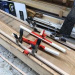
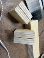
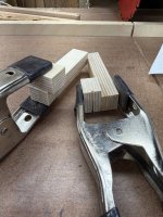
The gunnel halves are now dry fit and alignment marks added, using the strongback as a base. The extra sticks in the pic are for the actual epoxy operation, just marking stuff up here so it isn't going to slip/slide around much. The spring clamps are pretty useful and apply just a the right amount of force for gluing/epoxy work IMO

IMG_6222.JPG

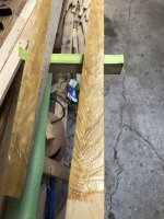
I like to epoxy skarf joints for 2 main reasons 1) epoxy has gap filling and on a long skarf the potential for gaps is real 2) colour control. First, saturate the cut with unthickened epoxy, then butter lightly with thickened epoxy. Position the 2 pieces and get the alignment marks close, clamp the extra rail to one side beyond the cut, align the marks and clamp the other side of the extra rail. Now the pieces can't shift or slide.
Add the center alignment block to keep the vertical aligned and add clamps to close the joint.

IMG_6226.JPG


Aiming to make this joint near invisible, so I mix cherry wood dust and cabosil at about a 10:1 mix ratio to maintain the right colour

IMG_6227.JPG

Next day we have

IMG_6228.JPG

Light scraping and light sanding and we have

IMG_6234.JPG

A before and after cleanup shot, the joints turned out pretty tight and I think once varnished, they will all but disappear (hoping)

IMG_6237.JPG

And the 19' long gunnels are born, now to cut that slot

IMG_6240.JPG

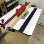
To cut the slot I decided that my router table and a 1/4" carbide spiral bit was a good idea, this is the router setup (new router table since B&C step) used

IMG_6242.JPG

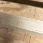
about 24" into the cut the piece jerked and the router speeded up, I hit the kill switch. From the top, I could just see this minor mark

IMG_6249.JPG

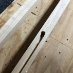
but underneath was a different story

IMG_6250.JPG

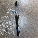
The bit had literally exploded

IMG_6258.JPG

I pondered what I could do to salvage the gunnel and decided that the top was barely marked and that the channel could be filled and repaired with epoxy. Alternatively, I could add a plug in that area as well. So I decided to do the epoxy first, as the channel needed to be repaired regardless and if the top cleaned up OK, then I bypass the plug option.

So I saturated the inside area with unthickened epoxy to harden the top and filled the damaged area with thickened epoxy and that worked pretty well.

IMG_6256.JPG

I still have to cut the channel, now I am a bit spooked about using the router, so did up a new jig for the radial saw and put on a 1/4" dado blade.

IMG_6262.JPG

IMG_6263.JPG

Did the alignment and made the 2 cuts, again, 1 hour to make the jig, 5 minutes to make the cuts, wish I had taken a few more minutes to check that alignment

IMG_6278.jpg

IMG_6280.jpg

This really isn't a big deal, centering is habit, not a requirement ... I will put the thinner side to the inside and add a chamfer, the water comes out easier and I have more gunnel on the outside to push water away from the edge.

Before installation the inside edge will receive a chamfer a 45 angle on the inside before installation and all the exterior corners will be rounded. Additionally, I will narrow (vertical thickness) the last 48" or so, by 1/4" (gradual slope 0" to 1/4" at end) as it approaches the stern/bow, the width support just isn't needed there as much.

Where thwarts/yoke and handles attach, a small length will be added to provide a thicker section for the attachment point, for something like a seat I would just use a longer section to distribute the load more (although I mostly use cleats now).

For now the gunnels are done, the rest of the work will be completed as they get installed, I learned the hard way not to add the rounds now and then try and add pieces to widen the gunnel at a point where the edge has been rounded.

The gunnels IMO, are one place that has the potential to add a lot of unnecessary weight, granted there is a balance between enough and too much, enough being determined by your individual usage. In this particular case, the gunnel may seem undersized, but there will be 2 thwarts and a seat providing lateral support, so there really isn't a large span where the gunnel isn't supported ... if you try reducing the gunnel size, this is something you have to consider.


Here are the gunnel weights as they progress to complete:

Rough Blanks : 7/8" x 1 1/8" @ 204" = 8.93 pounds
Planed Blanks : .688" x .75" @ 204" = 4.48 pounds
With Notch Cut: 3.46 pounds
Expected final: under 3 pounds (with inside chamfer, top sides rounded over and narrowing the ends)

A "traditional" gunnel is 3/4" x 3/4" inner and the same as an outer... that gunnel arrangement in cherry, for this build, would weigh ~13.5 pounds and in ash ~ 14.9 pounds

A point about the above, it shows a bias to my goal of reducing weight, this is not a concern for some folks , but I carry my boats a lot and I am not getting any younger, so I do worry about the weight ... and that will be reflected here ... a lot.

Adapt the material you find useful, ignore the rest ..... in the end "You have to do You"
 
Love the uniwale idea (very nicely done), I completely understand the "hold my beer" thing and anyplace you can lose 10 lbs is good.

Hard to believe that Cherry is $5.50 a board foot up there... I guess, for a board or two, ya do what ya gotta, but, if you ever need larger quantities, let me know. It wouldn't take many boards to offset the cost of fuel.
That's an all in cost ... ~3.60 US plus whatever local taxes you have
 
Glad you made the Uniwhale work !
My fear of the Uniwhale, would be it splitting ,at the 1/4" thick area, between the inwhale and out whale, while I was wrestling it into place saturated with Thickened epoxy.

Another thing the Uniwhale doesn't allow for Scuppers. I got to have scuppers.

Great data Brian.
know how to get the most out of that Radial Arm saw !


Jim
 
Thank you, @Cruiser, for taking the time to document this so painstakingly, even going as far as to cite your old threads. Your build threads are some of my favorites. I have a stripper build in me someday, and when the time comes I'll be much farther along in my learning curve thanks to this forum and contributors like you.

On the subject of the uniwale, the first time I set out to undertake a wood gunwale replacement project, the uniwale struck me as the simplest approach. It seemed like a little more preparation during the milling would more than offset the alignment, glue-up and shaping otherwise necessary. I'm surprised to hear its not used as often (exempting the desire for scuppers at least).
 
Last edited:
StrongBack Setup

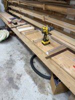
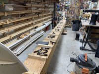
This isn't a new strongback and gets used for a lot of different things in the shop. So the first step for me is to remove any of the form attachment points that are still there and clean off (just an eraser, i use pencil)all of the drawn in mold locations.

Once verified it is still flat, re establish the centerline, then starting in the center, mark in all of the mold/form locations. Once those locations are marked, go over where each each mold support goes and make sure there are no surface imperfections, in my case checking for spilled epoxy, burrs, glue, splinters ... sand the area where the mold support goes to make sure it is flat.

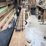
Just a note here, decide which side of the mold support the form/mold actually gets installed on and mark that on the SB. In this pic the SB is receiving the form supports and you can see the various squares and such ... there is also a piece of 1" x 6" lumber in the middle of the shot, it is cut to the spacing length and is used to check the position of the next line as I install the form supports (spacing is from the face of one form to the same face of the next). For this build the form support blocks got some attention to make sure they actually had vertical faces. Four foot lengths of straight 2" x 4" were planed flat on the 4" sides, then ripped in half on the radial saw. That gives a 90 degree surface to mount the form and 2 vertical attachment faces ... you can see the sides are clean and they are mounted cut side down.

Taking your time here and making sure that the form supports are flat and square is a good investment of your time IMO, a square vertical form, means less issues when you start adding strips.

IMG_6302.jpg

Time to position the SB and level it all up. I learned in the first build that this is the only section of the garage floor that is almost flat. The supports are shimmed until it is level end to end and side to side ... this is a good time to get a little picky IMO.

IMG_6450.jpg

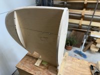
Time to install the Bow and Stern assemblies, there is a centerline on the mounting support and a matching one on the form, these are aligned, clamped drilled and screwed in place.

IMG_6458.jpg

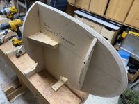
This will not be sufficient to hold that assembly in the right place at the front. It needs some sort of front support to keep it aligned. I notched a scrap of baltic birch ply so it was a tight fit, aligned the center ply on the strongback and fastened with a couple of screws. Operation was repeated at the stern.

IMG_6455.jpg

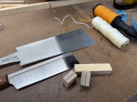
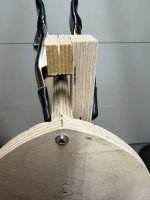
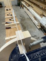
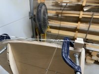
I still use a string to do the alignment steps ( I just don't have the need of a laser for anything else). I took a couple of the 3/4" baltic ply scraps ... there are 2 pieces at 3" x 1" and 2 pieces at 1" x 3/4". The center ply on the baltic birch 3/4" ply wood is the center, so I carefully used the small saw (Dozuki) to create a cut in the middle of that ply, then cleaned out using the bigger one (Ryoba) ... as an aside, I use them all the time, but had to look up the names to sound fancy

IMG_6460.jpg

IMG_6463.jpg

They got glued to the larger pieces

IMG_6466.jpg

and then mounted near the last form, since the chunk with the slot is the same material, that slot is perfectly aligned to the middle of the stem form. One thing about the forms (all the forms) is that you should mark the center line on the top, you can see it clearly in this shot. You need this to align the forms in the next steps.

IMG_6468.jpg

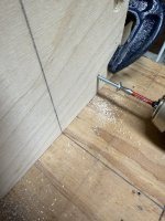
Each form gets lightly clamped in place (C clamp) string the line between and adjust the guide heights so the string clears the middle form by about 1/4" , how much you raise and lower is dependent on the rocker you have, then the clamps are tightened down. Tie it off to the C clamp at one end (here that is the stern) ... you can see the string sitting in the slot

IMG_6472.jpg

On the other end, a C clamp is placed near the bow end, the string has an elastic tied on and the elastic gets stretched and attached to the further c clamp ... this keeps that string under tension. Sometimes when you just tie it off it can sag.

IMG_6475.jpg

Now we can add the forms. Start at one end (bow in this build) and align the form center mark to the SB center mark, clamp the form to the form support

IMG_6481.jpg

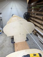
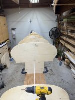
Check the alignment 2 ways, from the top, looking at the alignment mark and from the stern assembly end, sighting down the string and make sure the center line on the form shows sight alignment. This is difficult to show, but I hope these next two pics explain it
This is what it looks like if you are off to the side

IMG_6484.jpg

and this is sighting down the SB, see how the centerline gets hidden by the string when you are sighting directly down the middle. Checking the top mark is the same, except it is a little more difficult to get in position to do that.

IMG_6485.jpg

To actually fasten the form, drill an appropriate hole for the screw, 1/8" for a #8 screw in this case, the forms are 1/2" ply, so I have a second drill with a 3/16" bit with a tape flag at 1/2" ... the ply gets drilled before the screw is added. Now when you drive the screw, the form is pulled tight to the form support ... if the screw is biting in the form, that can't happen. You could unclamp the form to drill out the hole, but that adds a whole extra operation, the idea here is to have the screw go through the form ply and not really bite into the wood, but when it goes into the support it bites and then pulls the form tight.

Repeat until you are done ... check the spacing as you go, it is easy to put a form or support on the wrong side of a line

IMG_6494.jpg

I took a few extra steps this time and all the forms just went on right, completed in about 40 minutes
 
After looking at your pics a little closer ?
I wonder how much rocker you are going with ? It almost reminds me of the rocker on a Prospector.

Jim
 
Rocker is Bow 2" Stern 1"

The wind sticks are one way to make sure you are aligned longitudinally, I ended up using a level at both ends and shimming to alignment. Sticks may have been an easy check, but I am well into stripping at this point, so I will just add that to my list of build notes.

Brian
 
Last edited:
Back
Top