Lofting Canoe Molds from CanoeCraft tables
Preamble, Preamble ... I was going to use a BearMountain post I made, to answer a question here and it looks like the site is no longer functional. So I am posting the original from 2015 here to add to the DIY collection and have it available for reference.
Note: Corrections applied (20 Feb 2025) to converted values in
Adding Points from Table of Half-Breadths: Step 11&12, Step14&15 and step 17&18
Making the Stern Mold Drawing : Step 4&5
Preamble
It's winter, my garage isn't heated, I have a stripped Kipawa just waiting for fiberglass and it is currently -18C here .... what else is there to do, but plan my next canoe. I could just buy the plans (I will anyway), but that still wouldn't give me anything to do .... so I decided I would try and loft them from CanoeCraft (selected the Freedom 17).
(Note: The above was from 2014, I got sidetracked, Kipawa is completed and am finishing this in the winter of 2015)
This turned out to be a bit of a challenge, there didn't appear to be much in the forums but more questions on how to loft (likely my inability to search), most of the references I found were overkill for what I wanted, I did manage to find a few very helpful videos (notably from Jason Ekes, worth looking up). It has taken a few weeks (quite a few actually) to get enough information to feel confident enough to buy materials and make a few trials of what I thought I knew ... I will admit I wasted a few sheets of paper figuring out how to fix what I thought I knew.
My purpose here, is to share what I learned, on how to use the Lofting Tables for canoe building, which is pretty straight forward and not too complicated. It might be useful for a those folks trying to make sense of the tables, at the very least I have learned a new basic skill.
To be clear, I am not an expert, don't profess to have anything but a rudimentary grasp of the process and what you see here is my interpretation and application of what I have been able to learn and apply.
Materials Required
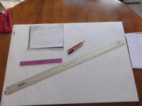
- grid paper at least 24" x 36" (Staples - Quartet® Graph Bond Flip Chart Easel Pad, 24" x 36", 50 Sheets ~$15)
- This paper is ruled in 1" squares
- straightedge, 36" with 1/16"divisions (Home Depot $9)
- large flat work surface
- fine tip heavy markers, pencils
- Canoecraft tables for Freedom 17 (there are 4... Heights, Half-Breadths, Bow Stem, Stern Stem)
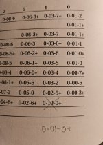
- make sure to check for corrections, for the Freedom 17 there is just one ... Station 1, WL18 correct 0-10-0+ to 0-01-0+
General Notes/Observations
When setting up the baseline (line everything is measured from), a bit of room is needed to elevate the molds higher than the sheer line.I am using 2", but this value is flexible, it just needs to be the same for all stations. If you want the stations to have a higher clearance (sheer to strongback), just increase this value to whatever you want.... just remember that this will also raise the top of the canoe and you have to reach and work there eventually.
One of the points of confusion I had, was the relationship of the "Table of Half-Breadths" (ToHB) and the "Table of Heights" (ToH).
What I have found is that they both describe the same shape, but from a different perspective. The halfbreadths are measured from the centreline out (waterline), while the heights are measured from the baseline down (butt).
Effectively, the mold can be made from either table or both. So ... to be clear, if you plot the "table of halfbreadths", you will get the correct shape and if you plot the "table of heights" you will get the correct shape. The data is not the same, and each set of points is different, but each describes the same shape.
I plotted all the points to get a better (more points) defined shape. Once you have plotted one complete mold, you will see that "Halfbreadths" gives more points near the sheer and "Heights" gives more points nearest the keel.
Making a Mold Drawing
Initial Page Setup
1. Lay the easel on the flat surface, long ways perpendicular to yourself
2. Pick the station number you want to make, I suggest a middle section to start with
- from CanoeCraft, I will use the Freedom 17 Station 13, as an example
3. From the bottom, measure up 2" on the left and right edges and put a dot
- Draw a line through the dots (full width) , I used a marker, but a pencil will work as well
- Label this line as "B" for Baseline
4. Measure to the middle of the sheet, locate the vertical line closest to centre
- draw a line (full vertical) and label "C" for centre
5. Starting where the baseline and centerline intersect, make and label hash marks, every 2", along the Baseline
6. Repeat the hash marking along the center line starting at the intersect
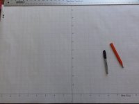
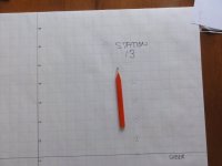
This is a pic of what it should look like. This was done on a table top, I found it easiest to work with the base nearest me, later I worked on an easel and found it easier to work from the top down ... both ways work just fine
Adding the Sheer Line
7. From the "Table of Heights", Station 13, locate the value for "Sheer"
- these values are organized as feet-inches-eigths with a plus sign indicating 1/16"
- historically I read that measuring rulers only went as fine as eighths, so the "+" indicated "and a bit" which was 1/16"
- in this case it is 0-06-2+ ,so 0 feet + 6 inches + 2/8" + 1/16", which summed up is 6 5/16"
8. From the baseline, measure up 6 5/16" on the left side, make a dot and repeat on the right side
- distance left and right doesn't matter, generally closer to the edge is easier
- use the ruler to draw a line full width through the dots, label it as "Sheer"
9. One other value for Station 13 is taken from here and that is the "Profile", this is the height of the mold along the centreline
- in the ToHs locate the "Profile" line (bottom), the value for Station 13 is 1-07-6+ or 19 13/16"
10. Measure from the Baseline along the centreline, 19 13/16" and make a hash mark. make a notation that this is the profile
- this will be the maximum height of this mold.
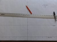
Should look like this now, this pic doesn't show the "Profile" point, it will show up in a later picture ...
Adding Points from Table of Half-Breadths
- The first point will be the sheer line, we have drawn in where the sheer occurs horizontally, we will now add where it stops
11. Looking at the ToHB under Station 13, using the value for "Sheer", we find 0-10-2+, this is 10 5/16" (0 feet plus 10" plus 2/8 plus 1/16")
12. From the Centreline, measure right along the "Sheer" we established earlier (step 8) and make a mark at 10 5/16"
13. Repeat step 10 going left
- The column down the left side of the table is labeled as "WL" (waterline) and gives horizontal values from the centreline at 2" intervals
- looking up the value of station 13 at WL2, yields a blank space, which makes sense, because the sheer is located at 6 5/16", so there is no canoe at that location
14. WL8 is the first value in the ToHB (for ST 13) and it is 0-10-2+ ... so this is 0' plus 10" plus 2/8" plus 1/16 ... or 10 5/16"
15. Using the horizontal gridline at the centreline 8" mark (WL8), measure 10 5/16" left and make a mark, repeat for the right side
16. Repeat this process for WL10 through WL18
Should look like this now, I mark WL points with a circle with a horizontal line, this makes it easier to check points later that don't seem right
Adding points from the Table of Heights
- The ToHs values are measured from the baseline markers, vertically and are called the Butt measure
17. Looking up the Butt 2" value we find it is 1-07-4+ or 19 9/16"
18. From the right hand 2" hash marker, on the baseline, measure vertically along 19 9/16" and make a mark
19. Repeat from the left hand 2" hash mark
19. Repeat for the Butt values at 4 and 6"
20. You can add all the Butt points, but I found that usually only a few points are needed to fill in points near the keel
21. If you intend to add a waterline marker on your actual molds, this is the time to add the line to the mold, for the Freedom 17, this is at WL 16". This will be a line on the graph paper, so measure along and make a hash line at 16" and label it as the Waterline
22. Repeat this process for all the station molds.
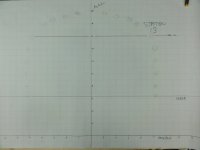
This pic includes the new points, waterline and the profile mark that was missing from the previous pic, I also mark each point with a circle and vertical line, again, just to be able to identify where the point came from in case it needs to be checked. You can make half molds and mirror to make the whole mold or you can chose to make the whole mold. I have chosen to make the whole mold, largely to support how I intend to transfer the shape to the actual wood molds (covered as we amble along).
The next bit is how to handle the Bow and Stern molds, this turned out to be interesting ... read that as I wasted a lot of paper.
Making a Bow or Stern Mold Drawing
These actually took the most "figuring" to execute properly and I did consume a few (quite a few) sheets getting it right.
Some things to note:
- the Bow and Stern tables are to the outside of the inner stem ... that is 3/4" more than we want
- you can't just subtract 3/4" from the measurements, as they are following a radius, so it won't be that simple
- there is more than 1 way to accomplish this, I will present the one I used
- the bow and stern assemblies work with 2 regular mold stations (0 & 1 for Bow, 15 & 16 for Stern), this is for the Freedom 17 and may vary for other models
- These directions will assume you have made a couple of Mold drawing and some of the plotting detail will be dropped
- For this section I have moved to the workshop and setup an easel, so I will be working from the top down
Making the Stern Mold Drawing
1. Draw the baseline 2" from the top of the sheet
2. Draw the Waterline 2" from the right side of the page (not the centre this time)
3. Mark in and label the 2" hash lines from were the lines intersect
- the Waterline is were Station 15 is located in relation to the stern, they will butt together on the strongback (eventually)
- Station 16 will be located 12" to the left of the Waterline (or Station 15)
4. Lookup the Profile value for Station 15 from the ToHs (1-07-2+ or 19 5/16")
5. Mark a dash on the waterline at 19 5/16" ... this marks the top of Station 15
6. Measure up 3/4" from the profile Hash you just made and make another hash and label it as Stern profile point, this is the profile mark (max height) for the stern (the inner stem will be on the stern mold and mold plus stem must match the ST 15 Profile)
7. Lookup the sheerline value (ToHs) for station 15 (0-04-6 or 4 3/4"), mark this on the waterline and label it as Station 15 Sheer
8. Measure over 12" from the waterline and make a dashed vertical line from the baseline down about 10" and label it Station 16
9. Lookup Sheerline line value (ToHs) for station 16 (0-03-5 or 3 5/8"), measure down the station 16 line and make a hash mark at 3 5/8" and label as Station 16 sheerline
10. Place a straightedge on the sheer marks for Station 15 & 16, draw a dashed line from the waterline to about the 20" line on the baseline, this is the sheerline for the stern mold
11. Locate the table of "Distance from Station 15 to aft edge of inside stern stem"
12. First point, WL 2" is 1-05-2+ or 17 5/16", measure left and place a dot
13. Repeat for WL4 through WL18
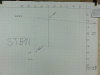
Your drawing should look something like this at this point, minus the second set of circled dots. The fainter dots to the left of the circles are plotted from the table, the circled dots are corrected for the 3/4" of the inner stern stem ( I didn't have a progressive picture without both sets).
Now we need to correct for the presence of the inner stem.
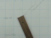
- requires a 3/4" batten, about 8-10" long ... but exactly 3/4" wide
- for the example, I am using a set of points on the section where the stern bends, as it demonstrates the method best
14. Locate the dots for WL 14 and WL 16, align the left upper corner of the batten with the WL14 dot, align the batten edge with the WL16 dot
15. The right upper corner is now the exact corrected location for the WL14 dot, mark it and circle it
16. Repeat this process to relocate each dot location, when you get to WL18, use the Profile mark (the -3/4" one) on the waterline, as the second alignment dot
I think this pic makes it pretty clear
17. Repeat this for the Bow, only change is to move the waterline to the left hand side of the page and use stations 0 & 1 of course
This is what the Bow drawing looks like
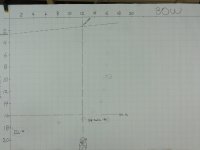
This gets all the station molds, Bow and Stern molds drawn. I will post more when I start actually making the molds with these drawings.
Preamble, Preamble ... I was going to use a BearMountain post I made, to answer a question here and it looks like the site is no longer functional. So I am posting the original from 2015 here to add to the DIY collection and have it available for reference.
Note: Corrections applied (20 Feb 2025) to converted values in
Adding Points from Table of Half-Breadths: Step 11&12, Step14&15 and step 17&18
Making the Stern Mold Drawing : Step 4&5
Preamble
It's winter, my garage isn't heated, I have a stripped Kipawa just waiting for fiberglass and it is currently -18C here .... what else is there to do, but plan my next canoe. I could just buy the plans (I will anyway), but that still wouldn't give me anything to do .... so I decided I would try and loft them from CanoeCraft (selected the Freedom 17).
(Note: The above was from 2014, I got sidetracked, Kipawa is completed and am finishing this in the winter of 2015)
This turned out to be a bit of a challenge, there didn't appear to be much in the forums but more questions on how to loft (likely my inability to search), most of the references I found were overkill for what I wanted, I did manage to find a few very helpful videos (notably from Jason Ekes, worth looking up). It has taken a few weeks (quite a few actually) to get enough information to feel confident enough to buy materials and make a few trials of what I thought I knew ... I will admit I wasted a few sheets of paper figuring out how to fix what I thought I knew.
My purpose here, is to share what I learned, on how to use the Lofting Tables for canoe building, which is pretty straight forward and not too complicated. It might be useful for a those folks trying to make sense of the tables, at the very least I have learned a new basic skill.
To be clear, I am not an expert, don't profess to have anything but a rudimentary grasp of the process and what you see here is my interpretation and application of what I have been able to learn and apply.
Materials Required
- grid paper at least 24" x 36" (Staples - Quartet® Graph Bond Flip Chart Easel Pad, 24" x 36", 50 Sheets ~$15)
- This paper is ruled in 1" squares
- straightedge, 36" with 1/16"divisions (Home Depot $9)
- large flat work surface
- fine tip heavy markers, pencils
- Canoecraft tables for Freedom 17 (there are 4... Heights, Half-Breadths, Bow Stem, Stern Stem)
- make sure to check for corrections, for the Freedom 17 there is just one ... Station 1, WL18 correct 0-10-0+ to 0-01-0+

General Notes/Observations
When setting up the baseline (line everything is measured from), a bit of room is needed to elevate the molds higher than the sheer line.I am using 2", but this value is flexible, it just needs to be the same for all stations. If you want the stations to have a higher clearance (sheer to strongback), just increase this value to whatever you want.... just remember that this will also raise the top of the canoe and you have to reach and work there eventually.
One of the points of confusion I had, was the relationship of the "Table of Half-Breadths" (ToHB) and the "Table of Heights" (ToH).
What I have found is that they both describe the same shape, but from a different perspective. The halfbreadths are measured from the centreline out (waterline), while the heights are measured from the baseline down (butt).
Effectively, the mold can be made from either table or both. So ... to be clear, if you plot the "table of halfbreadths", you will get the correct shape and if you plot the "table of heights" you will get the correct shape. The data is not the same, and each set of points is different, but each describes the same shape.
I plotted all the points to get a better (more points) defined shape. Once you have plotted one complete mold, you will see that "Halfbreadths" gives more points near the sheer and "Heights" gives more points nearest the keel.
Making a Mold Drawing
Initial Page Setup
1. Lay the easel on the flat surface, long ways perpendicular to yourself
2. Pick the station number you want to make, I suggest a middle section to start with
- from CanoeCraft, I will use the Freedom 17 Station 13, as an example
3. From the bottom, measure up 2" on the left and right edges and put a dot
- Draw a line through the dots (full width) , I used a marker, but a pencil will work as well
- Label this line as "B" for Baseline
4. Measure to the middle of the sheet, locate the vertical line closest to centre
- draw a line (full vertical) and label "C" for centre
5. Starting where the baseline and centerline intersect, make and label hash marks, every 2", along the Baseline
6. Repeat the hash marking along the center line starting at the intersect
This is a pic of what it should look like. This was done on a table top, I found it easiest to work with the base nearest me, later I worked on an easel and found it easier to work from the top down ... both ways work just fine

Adding the Sheer Line
7. From the "Table of Heights", Station 13, locate the value for "Sheer"
- these values are organized as feet-inches-eigths with a plus sign indicating 1/16"
- historically I read that measuring rulers only went as fine as eighths, so the "+" indicated "and a bit" which was 1/16"
- in this case it is 0-06-2+ ,so 0 feet + 6 inches + 2/8" + 1/16", which summed up is 6 5/16"
8. From the baseline, measure up 6 5/16" on the left side, make a dot and repeat on the right side
- distance left and right doesn't matter, generally closer to the edge is easier
- use the ruler to draw a line full width through the dots, label it as "Sheer"
9. One other value for Station 13 is taken from here and that is the "Profile", this is the height of the mold along the centreline
- in the ToHs locate the "Profile" line (bottom), the value for Station 13 is 1-07-6+ or 19 13/16"
10. Measure from the Baseline along the centreline, 19 13/16" and make a hash mark. make a notation that this is the profile
- this will be the maximum height of this mold.
Should look like this now, this pic doesn't show the "Profile" point, it will show up in a later picture ...

Adding Points from Table of Half-Breadths
- The first point will be the sheer line, we have drawn in where the sheer occurs horizontally, we will now add where it stops
11. Looking at the ToHB under Station 13, using the value for "Sheer", we find 0-10-2+, this is 10 5/16" (0 feet plus 10" plus 2/8 plus 1/16")
12. From the Centreline, measure right along the "Sheer" we established earlier (step 8) and make a mark at 10 5/16"
13. Repeat step 10 going left
- The column down the left side of the table is labeled as "WL" (waterline) and gives horizontal values from the centreline at 2" intervals
- looking up the value of station 13 at WL2, yields a blank space, which makes sense, because the sheer is located at 6 5/16", so there is no canoe at that location
14. WL8 is the first value in the ToHB (for ST 13) and it is 0-10-2+ ... so this is 0' plus 10" plus 2/8" plus 1/16 ... or 10 5/16"
15. Using the horizontal gridline at the centreline 8" mark (WL8), measure 10 5/16" left and make a mark, repeat for the right side
16. Repeat this process for WL10 through WL18
Should look like this now, I mark WL points with a circle with a horizontal line, this makes it easier to check points later that don't seem right

Adding points from the Table of Heights
- The ToHs values are measured from the baseline markers, vertically and are called the Butt measure
17. Looking up the Butt 2" value we find it is 1-07-4+ or 19 9/16"
18. From the right hand 2" hash marker, on the baseline, measure vertically along 19 9/16" and make a mark
19. Repeat from the left hand 2" hash mark
19. Repeat for the Butt values at 4 and 6"
20. You can add all the Butt points, but I found that usually only a few points are needed to fill in points near the keel
21. If you intend to add a waterline marker on your actual molds, this is the time to add the line to the mold, for the Freedom 17, this is at WL 16". This will be a line on the graph paper, so measure along and make a hash line at 16" and label it as the Waterline
22. Repeat this process for all the station molds.
This pic includes the new points, waterline and the profile mark that was missing from the previous pic, I also mark each point with a circle and vertical line, again, just to be able to identify where the point came from in case it needs to be checked. You can make half molds and mirror to make the whole mold or you can chose to make the whole mold. I have chosen to make the whole mold, largely to support how I intend to transfer the shape to the actual wood molds (covered as we amble along).

The next bit is how to handle the Bow and Stern molds, this turned out to be interesting ... read that as I wasted a lot of paper.
Making a Bow or Stern Mold Drawing
These actually took the most "figuring" to execute properly and I did consume a few (quite a few) sheets getting it right.
Some things to note:
- the Bow and Stern tables are to the outside of the inner stem ... that is 3/4" more than we want
- you can't just subtract 3/4" from the measurements, as they are following a radius, so it won't be that simple
- there is more than 1 way to accomplish this, I will present the one I used
- the bow and stern assemblies work with 2 regular mold stations (0 & 1 for Bow, 15 & 16 for Stern), this is for the Freedom 17 and may vary for other models
- These directions will assume you have made a couple of Mold drawing and some of the plotting detail will be dropped
- For this section I have moved to the workshop and setup an easel, so I will be working from the top down
Making the Stern Mold Drawing
1. Draw the baseline 2" from the top of the sheet
2. Draw the Waterline 2" from the right side of the page (not the centre this time)
3. Mark in and label the 2" hash lines from were the lines intersect
- the Waterline is were Station 15 is located in relation to the stern, they will butt together on the strongback (eventually)
- Station 16 will be located 12" to the left of the Waterline (or Station 15)
4. Lookup the Profile value for Station 15 from the ToHs (1-07-2+ or 19 5/16")
5. Mark a dash on the waterline at 19 5/16" ... this marks the top of Station 15
6. Measure up 3/4" from the profile Hash you just made and make another hash and label it as Stern profile point, this is the profile mark (max height) for the stern (the inner stem will be on the stern mold and mold plus stem must match the ST 15 Profile)
7. Lookup the sheerline value (ToHs) for station 15 (0-04-6 or 4 3/4"), mark this on the waterline and label it as Station 15 Sheer
8. Measure over 12" from the waterline and make a dashed vertical line from the baseline down about 10" and label it Station 16
9. Lookup Sheerline line value (ToHs) for station 16 (0-03-5 or 3 5/8"), measure down the station 16 line and make a hash mark at 3 5/8" and label as Station 16 sheerline
10. Place a straightedge on the sheer marks for Station 15 & 16, draw a dashed line from the waterline to about the 20" line on the baseline, this is the sheerline for the stern mold
11. Locate the table of "Distance from Station 15 to aft edge of inside stern stem"
12. First point, WL 2" is 1-05-2+ or 17 5/16", measure left and place a dot
13. Repeat for WL4 through WL18
Your drawing should look something like this at this point, minus the second set of circled dots. The fainter dots to the left of the circles are plotted from the table, the circled dots are corrected for the 3/4" of the inner stern stem ( I didn't have a progressive picture without both sets).

Now we need to correct for the presence of the inner stem.
- requires a 3/4" batten, about 8-10" long ... but exactly 3/4" wide
- for the example, I am using a set of points on the section where the stern bends, as it demonstrates the method best
14. Locate the dots for WL 14 and WL 16, align the left upper corner of the batten with the WL14 dot, align the batten edge with the WL16 dot
15. The right upper corner is now the exact corrected location for the WL14 dot, mark it and circle it
16. Repeat this process to relocate each dot location, when you get to WL18, use the Profile mark (the -3/4" one) on the waterline, as the second alignment dot
I think this pic makes it pretty clear

17. Repeat this for the Bow, only change is to move the waterline to the left hand side of the page and use stations 0 & 1 of course
This is what the Bow drawing looks like

This gets all the station molds, Bow and Stern molds drawn. I will post more when I start actually making the molds with these drawings.
Last edited:

