• Happy Birthday, Ansel Adams (1902-84)! 📷🌄

An extra trippy Merlin.

Joined
Aug 10, 2018
Messages
1,511
Reaction score
2,189
Location
Blairsville, PA (about 30 mi E of PGH)
The game plan coming into winter this year was to finish the Raven that I'd started and to get another solo finished before spring. This one will be built from White Pine & Cherry. These woods should look nice but I expect them to be a more bland combination than the Tamarack / Sassafras or even the Aspen / Cherry that I've used previously and that's good... I've been wanting to color the outside of a stripper and a more mundane wood might be just the ticket.

For a few years now, I've had pdf plans for a Merlin (from Northwest Canoe) and, while I think it will be a very similar hull to the Freedom solo that I built (maybe a little more rocker and a little less freeboard), I like the Freedom and I see no harm in another boat that's similar to one I already like. Besides, I'd set the Freedom up for tripping with the seat moved really far to the rear and I can set the Merlin up as a day tripper with the seat more centralized.

I'm also planning on hanging this seat from the gunwales because I haven't done that yet and I should try it. I'll eventually build a hull with inner and outer stems for that same reason but it won't be this hull. This one will be stemless and already has enough experimental stuff planned IMO

The plans were pdfs and the local print shops could print them but only on heavy weight paper that was just short of card stock. One of them (the one I use for waterproof maps) suggested finding someone able to print blueprints so I contacted an architect friend. He loved the idea of building a canoe this way, had the plans printed within hours and refused payment as long as I sent him pictures of the canoe.

Deal.

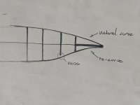
There was some question about the scale (I guess engineering drawings typically include a letter that indicates scale and it was missing?) so my first order of business was to lay out the plans and make a few measurements to verify the size.

IMG_20250213_174447419.jpg

Satisfied that we were in the right ballpark, the next item of business was the shop.

I'd put bead on a mountain of White Pine & some Cherry strips when I was milling the Larch for the last build and the shaper was still set up for the coves so I spent about 2 1/2 hours cutting the coves and trimming off any places where the strip had been cut thin or the bead or cove had not cut well. That done, I moved all strips to the infeed table near the strongback and moved the Raven to the now empty offloading table.

IMG_20250214_192700826_HDR.jpg

That being accomplished, I now had the strongback empty for laying out station molds and I ran to the local Lowe's for 2 4x8 sheets of 1/2" OSB and had them cut them in 1/2 for me (I like buying local but neither of the mom & pop lumber yards near me have a panel saw to cut the sheets).

I extended the center line to the edge of the paper, cut two 3/8 inch holes in that center line so that I could align it with the center line on the OSB and used the factory edge of the sheet as an additional guide for square. I measured out 5 inches from each side of the centerline for the form bases & left them long so that the stems will be at least 3 inches above the strongback. (the reason for this will be clear just before I'm ready to glass)

DSCN3660.JPG

In all, I spent about 5 (very snowy) hours in the shop today and I'm ready to cut out the forms. I was hoping to do that outside & reduce the amount of dust in the shop but that's unlikely given the short range forecast (and I'm not waiting for nicer weather).

DSCN3661.JPG

A keen observer will note that I've moved the band saw. This was necessary because the Pine strips are 14 feet (longest strips I've used so far) and the saw was in the way. That same keen eye might note that I've drawn a line 12 inches up from the factory edge (bottom of the form). That will be used to align the forms with a laser level once they're cut out & sanded to the pattern lines. (hopefully tomorrow but we'll see)
 
Good choice. I built a slightly shortened version of that Merlin. It is a fast boat and tracks really well. Watch out when crossing eddy lines, this canoe wasn't designed for that. You may find that the last 2 stations in the stern need additional fairing. I'm pretty sure I didn't make a mistake when cutting the forms. Good luck

Mark
 
Northwest Canoe, modified the Original Bruce Kunz Merlin.
A good move, beings you have the PDF file, see if you can enlarge by .38% You will then have the 38 Spl. You will need to go to a 12.5" form spacing, and yes as Mark states above, you will need to Fair the station.
I know I did.

I use 6# Fish line to align forms, I don't think a laser is as accurate.

Jim
 
Thanks guys, I'll certainly pay extra attention to those 2 stations.

I looked into buying the 38 special plans a few years ago when they were (briefly) available but I didn't get it done. For now, I'm fine with the smaller hull; I've got the Raven for large volume and my only reservation on the Merlin is only 9 inches of freeboard. I suspect this will be a day tripper and the Raven will be the travel hull but we'll see...

I'm curious how a string line could be more accurate than a laser line... ?
 
I'm curious how a string line could be more accurate than a laser line... ?
Accuracy is in the eye of the builder. Some are happy if their forms are a1/4" off. That's just not me. How will a hull preform, if the forms are off a 1/4" ? I don't know.
How thick is the laser beam projection ?
I can visually inspect the fish line, anytime during the set up and building process,even if I move the strongback, and I do. The fish line makes it easy, to inspect, insuring nothing has moved, and yes things move. can you do that with the laser ?
Can you verify the base line with the centerline once the forms are in place ?

Marks on the wall, don't matter if you bump the strongback.

the KISS method, comes into play here, you can spend a lot of time and money on things, that aren't any better than the old tried and true method.

Oh, a note on enlarging the NW Merlin, it is rockered, the original 38 Spl., is not ! Fairing the forms is always a good idea, with any set of forms !

Good question !

Jim
 
Gamma, one other tip on using these plans. You'll notice that the keel line on the stem forms does not meet up with the keel line on last form on either end the way they usually do on canoe plans. At first I thought the designer left a space to accommodate an internal stem, but no, these plans are for stemless construction. That space is apparently there to keep that part of the form (where they meet) out of the way during construction. Here is the quote from Dan Meer at NW Canoe and a picture he sent.

"With our plans, It is normal for the stem form to mount slightly down from the first and last stations (you can see it in the attached picture). This is because as the strips come together from different angles at that location it is best to have that space there."

You'll notice he doesn't start tapering the stem form until 5 or 6 inches out from the last (or first) form. I hope this makes sense, Mark


Forms set up.JPG
 
Northwest Canoe, modified the Original Bruce Kunz Merlin.
A good move, beings you have the PDF file, see if you can enlarge by .38% You will then have the 38 Spl. You will need to go to a 12.5" form spacing, and yes as Mark states above, you will need to Fair the station.
I know I did.

I use 6# Fish line to align forms, I don't think a laser is as accurate.

Jim
Hi Jim! Is it really true that you will get the 38 Spl. by scaling the NWC Merlin plans?
A wise man once told me that the North West Merlin was not the parent of the 38 Spl. That the the 38 Spl. was a Bruce Kunz creation and that It was an enlargement of Bruce's original Merlin.

I've laid the plans on top of each other to compare the two but since they call for different spacing between stations and the fact that the 38 Spl. has 13 stations while the NWC Merlin has 14 makes this comparison difficult to read. They appear to be quite similar, though not the same. The Kunz 38 Spl. has no rocker while the NWC Merlin do have some in the first and last three stations. Here's the Kunz 38 Spl in black and the Scaled up NWC Merlin in red.38splblack merlinred scaled3point8.jpg
 
Last edited:
I Stand Corrected ! Your plan overlay is enlightening !
I should have done that !
If you take out the Rocker from the NWC Merlin ? You pretty much have the same forms, below the waterline, as the 38.
Oh, I see the Shearlines are slightly different also.
I'd like to know Who drew up the NWC Merlin ? Maybe Dennis Davidson ?
Who ever, drew up the plans, certainly had knowledge of Bruce's 38.

Thanks Stripper, for the enlightening comparison !

Jim
 
You'll notice he doesn't start tapering the stem form until 5 or 6 inches out from the last (or first) form. I hope this makes sense
Makes perfect sense and I HAD suspected that the plans were drawn for stemless. I remembered that Jim said he dropped the stem forms by 1/4 inch and thought that they'd already done it. Not being CERTAIN, however, I dropped them an extra 1/8 inch. (A little more rocker never hurt anybody, right?)

Here's the Kunz 38 Spl in black and the Scaled up NWC Merlin in red.
Looks like I'll need to scale up the Merlin if I want a bigger hull. My biggest objection to the Freedom is not enough rocker (although, in fairness, I did not drop the stem forms as Jim suggests... Might need a do-over on that one...

Accuracy is in the eye of the builder. Some are happy if their forms are a1/4" off. That's just not me. How will a hull preform, if the forms are off a 1/4" ? I don't know.
That's exactly why I use a laser to align my forms. I don't trust the strongback to be true any more than I trust the floor of the shop but light will travel in a straight line (at least for 18-20 feet). I'll explain in today's post:

I spent several hours in the shop after work & made really good progress.

First order of business was to cut the forms apart. I'd laid out the center line of each form in pencil and the dividing lines between the forms in black sharpie. I took a circular saw to them and I'll probably use a red or blue sharpie next time. There were 3 times when I nearly started sawing the centerline instead of the divider & a different colored pencil or more contrasting sharpie would prevent this.

(note the line 12 inches up from the edge of the OSB. This was not on the plans but I put it there for alignment reasons)

DSCN3662.JPG

Once separated, I cut the forms with the band saw, staying wide of the lines and then used the oscillating belt sander to get the final shape.

DSCN3663.JPG
DSCN3664.JPG

That done, I clamped a square to the last strongback station. This square had previously had sharpie lines marked at the 12 inch mark and the center of the longer arm.

DSCN3665.JPG

I then grabbed my laser level jig, clamped it to the step stool and shimmed accordingly until the lines were both plumb & level. I used a measuring tape to verify that the line was 12 inches above the strongback at the bow and the stern and used the centerline of the strongback to verify that it was properly aligned.

DSCN3669.JPG
DSCN3666.JPG

(note: I'd previously tried to make a detachable extension for the strongback but the vibration of attaching to forms moved the laser level a bit. It worked better to have it separated from the strongback & several feet away)

Having verified alignment, I started at the stern (closest to the door) and, using the centerline and the line I'd added 12 inches from the edge, lined these two up with the crosshairs of the laser level, clamped the form to the station support and screwed it tight.

DSCN3672.JPG


I feel that, in this way, I've eliminated any variation to the best of my ability and the alignment is as good as I can get it. As a final check, after all stations were installed, I lifted the laser level off of the step ladder and lined it up from above. It hit the centerline on all station molds so I was satisfied that it'll do.

One "whoops" moment came while checking for fairness. I grabbed a pine strip (about arm's length long) and moved it along the forms to be sure that it would contact the forms evenly when making contact with 3-4 forms at the same time. All was good until I came to the penultimate form. I'd remembered that Jim & Mark had (above) said that this station would need faired but I guess I was expecting it to need shaved down and not built up.

DSCN3673.JPG

I've got solid contact at the sheer and the keel line but I'm almost 3/8 inch away 1/2 way between the two. Now the dilemma: I can remake the form, estimating where it should be and sanding it until it's right or I can shim the strips as I go. If I remake the form, I won't be able to use the laser to align it and I'll have to rely on a string line & level to get it reinstalled (or remove all of the forms ahead of it- which is not going to happen). I'm sure either will work but I'm not sure which way I'll go.

Not really a critical decision right now as the next item is to make the strongback a rotisserie.
 
...If you take out the Rocker from the NWC Merlin ? You pretty much have the same forms, below the waterline, as the 38.
Oh, I see the Shearlines are slightly different also. I'd like to know Who drew up the NWC Merlin ? Maybe Dennis Davidson ?
Who ever, drew up the plans, certainly had knowledge of Bruce's 38.
Thanks Stripper, for the enlightening comparison !

Jim
Maybe this comparison should have gone in a separate thread but just to wrap it up. Yes, I think that they do come from the same source which probably is the Kunz original Merlin. If the keel line of the NWC Merlin was flattened then it looks like they would be near identical under the waterline. The plans for the 38 Spl. does not have any sheer line indicated so I have estimated that in the drawings. It also looks like the NWC Merlin has a little bit different shape in the tumblehome area. At center station, the 38 Spl. sides actually flare out under the gunwale while the NWC Merlin goes straight up. If the NWC Merlin had totally flat rocker and was scaled up 3.8% then it could be considered a refined Kunz Merlin (or actually, a refined Kunz 38 Spl.)
I wonder what that rocker on the NWC Merlin does though? I suspect that on a boat strictly intended for paddling on lakes or flat water a straighter keel line would be desirable to keep maximum tracking and straight glide.

All thanks to you Jim. Without you I wouldn't have been able to do this comparison, so thank you!

Sorry for the drift Gamma, and thank you for taking us along on this build. I look forward to the seeing your canoe take shape!
 
Last edited:
...One "whoops" moment came while checking for fairness. I grabbed a pine strip (about arm's length long) and moved it along the forms to be sure that it would contact the forms evenly when making contact with 3-4 forms at the same time. All was good until I came to the penultimate form. I'd remembered that Jim & Mark had (above) said that this station would need faired but I guess I was expecting it to need shaved down and not built up.

View attachment 145506

I've got solid contact at the sheer and the keel line but I'm almost 3/8 inch away 1/2 way between the two. Now the dilemma: I can remake the form, estimating where it should be and sanding it until it's right or I can shim the strips as I go. If I remake the form, I won't be able to use the laser to align it and I'll have to rely on a string line & level to get it reinstalled (or remove all of the forms ahead of it- which is not going to happen). I'm sure either will work but I'm not sure which way I'll go.
Gamma.
I don't know if this is just how you rigged that test strip up to take this photo or not, but when you clamp the strip like that it "re-curves". This is not the way the strip lays on the hull naturally. When clamped like that it will pivot over the first station and therefor "fly" past the second station without touching. I think that is probably most of the issue you are having. Instead of a clamp you could just use a piece of tape at the end of the strip and wrap that around the bow/stern stem station. It will allow the strip to lay down naturally over the intended curve of the hull. Some fairing might of course be needed but it shouldn't be nearly that much.
 

Attachments

  • 1000009286.jpg
    1000009286.jpg
    76.1 KB · Views: 4
Yes, the curvature between the stem form & station #14 is due to the clamp I used (I needed one hand for the camera and have only 2). The gap is present when holding the strip by hand but is not quite as pronounced (I should have thought to tape it at the stem as that would have reduced the deflection.

Leaning toward shimming that station instead of remaking it. I can measure & mark it as I go up and, if I eventually remake this hull (I'm still hopeful of building a Sumac boat) I can remake the form using the measurements.
Maybe it's not so bad after all? How much distance do you have at station #13 when just holding the strip with your hands (or using tape)?
Maybe you could get away with slight fairing on station #12 and #14 instead of building up #13? Or maybe a combination. You would probably need no more than just a few layers of gaffer tape partially taped over station #13 then.
 
I wonder what that rocker on the NWC Merlin does though? I suspect that on a boat strictly intended for paddling on lakes or flat water a straighter keel line would be desirable to keep maximum tracking and straight glide.
The NWC Merlin is a hard tracking boat. I gave away the one I made, but have paddled it on a number of occasions in flat and moving water. Upstream travel and crossing eddy lines is done with caution, or not at all. The rocker measurements are deceiving since the keel line is flat along 2/3 of its length. My Winters Kite has similar specs on paper, but is a joy to paddle in moving water because the rocker is carried past the centerline. There are too many missing bits of information with trying to compare canoes with typical specs provided by the manufacturer.

Leaning toward shimming that station instead of remaking it.
I ended up taking some away from station 12 and 14 and building up with a little tape on station 13.
 
I've used tape to buildup thickness on forms and once, when the difference was too large for just tape, I cut some really thin strips on the bandsaw and laid them over the form and taped them down.

Alan
 
In my experience, I repositioned the forms by adjusting the cleats and forms, to make things Fair.

Now that you have the forms in place, You need to insure your stem forms are perfectly vertical, or at least aligned with each other.
This Is a trick I learned from the MCA Builders book.
Here is a simple pic, that should illustrate aligning the stem forms.
Simply staple, or clamp scrap strips to the stem forms vertically.
and with your Eyeball verify .


c64ee6cc-d359-46fc-a278-744e9c78d522.jpg


Jim
 
Last edited:
Gamma, if you have a gap of 3/8" to build up, it may be less work just to remake/rework that form, you have a perfect alignment on the form before and after, so you really won't have much issue getting decent alignment IMO.

Do your correction measurements, cut a piece of form material, glue it to the edge, trace in the new shape and cut and sand to shape ... you can use anything to build up the area.

I had the same issue on my last boat, this was the fixed form

add material

IMG_1548.jpg

Draw in new shape

IMG_1550.jpg

Cut and sand off excess

IMG_1553.jpg

Brian
 
Not really a critical decision right now as the next item is to make the strongback a rotisserie.
Rotisserie ! Now we are Talking !
The first one I saw was in Wisconsin. Martin Van, a professional canoe builder, had one.
That was my inspiration for Tilting my strongbacks.

He was able to get a full 90 degree rotation. Using Plastic cement, that came as a powder, and mixed with water, was his strip glue, of choice. He stated that the mixture allowed him to glue up 9 strips, before setting too hard to use.

Of course he beaded and coved the strips.
Rotating the strongback, made scraping and sanding easier.
Martin made a very nice canoe ! He also used staples.
He and his wife, working 40 hours a week, could turn out a canoe in three weeks.
I was lucky to have met him ! And learn, at least some of his methods. This was during a tour sponsored by the Minnesota Canoe Assc.

Looking forward to your Rotisserie !

Jim
 
1739937626295.png


Sorry For mixing this in with Gamma 1214's Thread ! But looking at the form spacing, and comparing it to a friend's build.
My friend started with the original Kunz designed 38. He forgot about the 12.5" form spacing. Instead went with the 12" spacing as used in most designs. We Nick named it the " Pomeroy Spl."
It paddled OK, but it wasn't a 38 Spl.

That is what NWC appears to have done, but adding an extra center form, to get the length they wanted.

So in review, The NWC Merlin, will not preform, like the Kunz 38 Spl.
 
Last edited:
Back
Top