• Happy Boxing Day! 🎁📦💰

Multiday Adventure Race Canoe - Composite

Joined
Aug 8, 2016
Messages
73
Reaction score
76
Welcome to an unconventional build thread. I enjoy reading these sorts of things and have learned so much from others that I am happy to post my own projects. I welcome community input and hope we can learn a few things along the way. This is a construction forum, so no need to tell me I'm crazy (I'm fairly aware of that) or that I should just buy a faster secondhand boat. I'm sure you all appreciate the personal satisfaction that comes out of a home build, and that's what I'm in this for too. I'm an amateur and this is a hobby: There's a good chance the boat will be a failure, or will not live up to my expectations- and that's okay by me. I say 'unconventional' in that I really haven't seen this type of canoe build executed and published before. A lot of my research has come from composites forums and power/sail boat construction forums.

Design Goals:
-Purpose is solo multiday adventure racing (340, Safari, Border Route, etc). Unbounded creativity, it seems, can only live in the unlimited class events.
-Secondary purpose is fitness paddling: going hard and fast for 1-3 hrs- for fun.
-Lightweight enough to significantly effect portage weight (grand portage is 9 miles). Current calculations are targeting a 20-25lb boat.
-Design Displacement for Paddler+Boat+3 days equipment= 225lbs.
-Large favored secondary stability for a tired paddler.
-Able to be efficient with single and double blade.
-Able to be re-entered in deep water.
-Ruddered to manage beam winds for long distances.
-Design favors deep open water vs shallow narrow water.
-All-day speed will only be limited by 1) all day stability [it is much faster paddling on the water rather than in the water] and 2) my level of fitness.

Build Goals:
-Take a hull from design all the way to finished boat.
-Use vacuum resin infusion for final boat assembly.
-Target 60% fiber volume ratio for lightest/strongest boat.
-Unlimited fiber set-up time for busy solo builder dedicating "a few hrs here-and-there."
-Necessitates male plug and female mold- relatively high waste for non-production canoe.
-(Much driving the choice of build technique is a personal desire to learn the vacuum infusion process and see if I can do it at full scale- there is a bit of a gamble as to whether or not it will work or if I will ruin $800 worth of materials in a single 40 minute infusion.)​
-Timeline: unknown. This might take awhile, but I hope to have it in the water this summer.

Inspiration:
- First, I have to thank Alan Gage, who has helped with many questions and knows far more about design dynamics (and paddling in general) than I do. He sent me a lines plan of his X-canoe, of which this design is really just a big set of modifications. You are encouraged to reference his well-documented build here: http://www.canoetripping.net/forums/forum/general-paddling-discussions/diy/19929-x-canoe-build
- My current workout/solo tripping boat is a Magic. I have paddled it in waves big enough to hide the horizon (terrifying, but a testament to stability) and I feel like my cruising speed is limited by the design.
-I almost sent away $4k for a Blackwater solo: but thought I could try my hand at a more extreme design while realizing the cost savings and satisfaction of a home build instead. Considering that as an alternative, even with plug and mold construction I am still far under budget.
-I have never seen a Texas/Spencer canoe in person (and online searching shows only few photos and no real specifications), but I think this design is somewhere close to a Landick II.


Specs:
-19'6" length overall
-waterline beam at design displacement: 22"
-displacement at 3.5" waterline: 226lbs
-finished weight: 20-25lbs.
-Rocker: 1.5" bow, 0.75" stern.
-most other standard measurements don't describe the boat well, due to the unconventional design.
 

Attachments

  • photo11628.png
    photo11628.png
    1.2 MB · Views: 31
The design began by lofting Alan's X-canoe in CAD. I then played with it for a few months. The ghosted photos show how the design differs from Alan's boat. The wetted surface below the waterline is essentially the same: the only major difference underwater is 9% narrower beam at design displacement, and 12" longer overall. Despite the extreme shape of the boat, the photo shows the waterline as a slender swede form with center of mass (buoyancy of the underwater volume only).

Above the waterline, the front is pinched-in to get a clean vertical paddle catch with either single or double blade paddle. The bow has a good flare to shed waves and prevent the long boat from pitching over if the nose is buried on a downwind run. The most distinctive feature is the hips that flare from just behind the paddling station to the stern: They are the keepers of secondary stability. If the boat is rolled over at all, the skinny 22" waterline instantly widens to provide righting force. A good amount of the bow/stern will be enclosed to both stiffen the hull and create flotation tanks. There will likely be some sort of removable spray deck.

To model the paddling station in full scale, I printed two forms and made a cardboard "cockpit" to sit in. The front is skinny, but I like that the hips are right behind me. I then put clamps and bungee lines in my magic to see how it would feel paddling while confining me to a skinny station. I think the spacing of the rails will be fine, and I found that my feet actually deliver more power/better ergonomics if they are closer together. What I can't test (and the biggest unknown variable) is just how tippy will it be. Am I going too far in the name of speed? I can't really find out until it's floating.
 

Attachments

  • photo11630.png
    photo11630.png
    965.7 KB · Views: 19
  • photo11631.png
    photo11631.png
    896.3 KB · Views: 18
  • photo11632.png
    photo11632.png
    141.1 KB · Views: 18
Last edited:
The layup is going to be mixed composites: Carbon for its stiffness and light weight, Innegra for its resilience and light weight, and an outer veil of thin glass for scratch resistance/refinishing protection. Foam bottom panel and foam ribs. Integrated foam gunwales. I have been practicing the infusion techniques for about a year, and in preparation for this build have tested layup schedules and epoxies to gain confidence that I can in fact pull off a full-scale infusion. Again, this is a hobby for me and I enjoy the learning probably more than the finished project.


Proposed layup schedule is (outer to inner):
1.4oz glass veil
5.7oz hybrid cloth "chickenwire" carbon warp/innegra weft
3.6oz innegra plain weave
core: 6mm 5lb density PVC foam
6oz carbon twill

The final test was a 16" section of half of a hull. It had all design features of the proposed boat including foam core floor, ribs, gunwales, layup and dimensions. I made the mold by bending a sheet of polycarbonate. (on the backside of the polycarbonate, you can see a twill pattern where a former test stuck to the mold!) The test was also run in shop conditions and with processes that would be the same as a full boat. The epoxy viscosity is very sensitive to temperature. I can control small infusions using heating pads, etc, but a full boat would have to be done in the garage: I do have a radiant tube heater on the ceiling that I think will be enough to control temperature of the mold/infusion. Tackifier was used to fix the dry fiber. There were some problems discovered during the test, but the strength of the result has me wondering if I can go lighter on the fiber layup. My 50lb 6 year old can stand on it without deflection. He is very interested in everything I do, but always confuses "carbon fiber" with "carbon dioxide". It is too cute to correct him when he asks if I am making more carbon dioxide.


https://youtu.be/RyBUr2FOAp8
 

Attachments

  • IMG_1721.jpg
    IMG_1721.jpg
    610.8 KB · Views: 4
  • photo11633.jpg
    photo11633.jpg
    610.8 KB · Views: 3
Last edited:
Looks good. I don't have a lot of time right now but do you have resistance calcs for the hull? I'd be worried that although the long hull might be faster that it might not be feasible to push it that hard for an extended period of time. Delftship can provide those calculations and it's interesting to see how changes in the hull affect the resistance at different speeds. For long distance I'd be looking for a hull that offers the lowest resistance at an output you can sustain for hours on end.

Alan
 
Great Thread Start ! Muddy !

This will hold the interest of a bunch of us ! I hope you don't mind questions and inputs from others ?

Are you planning to make a female mold for this canoe ?

Great video by the way !

Is weight going to be an issue ?

If it is? Then you can get by with just using partial layers of cloth. and reduce the cloth running up from the waterline. Especially if you go with a pedestal seat.

I'm sure you've seen the videos of Factory canoes being struck by a hammer repeatedly! Note they are just striking the bottom, not the sides !

Alan is a great resource !

Jim
 
This is going to be fun to follow!

Somewhere I read (can't find the ref) that the original Landick was based on a J-boat in the bow and a proboat in the center/stern. It sounds like your design is quite a bit skinnier than a 3x27 proboat (3.5x22?), almost like an open surfski with added volume above the waterline. Do you have a target seat hight?
 
Looks good. I don't have a lot of time right now but do you have resistance calcs for the hull? I'd be worried that although the long hull might be faster that it might not be feasible to push it that hard for an extended period of time. Delftship can provide those calculations and it's interesting to see how changes in the hull affect the resistance at different speeds. For long distance I'd be looking for a hull that offers the lowest resistance at an output you can sustain for hours on end.

Alan

Thanks. The consistent variable is the displacement. I weigh a fairly stable 175 when fit. With 20lb boat and 30 lbs of gear/food I need to target a displacement right around 225. To be honest, I took a guess that a slightly narrower/slightly longer boat (same displacement) would offset the additional wetted surface in terms of total resistance. You are right that it all depends on the speed. I looked at my last two years of GPS tracks for anything over 6 hrs and found that I push magic all day at 4.75mph or so. (I also found that any tiny pee break completely kills your average!)

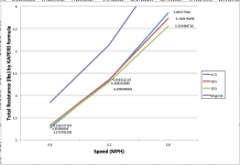
I think Delftship uses the KAPER formula to estimate resistance. I am bound to Mac software and haven't had a good chance to learn that program. Instead, I found a spreadsheet that SeaKayaker magazine used based on the KAPER formula by John Winters. It was published in 2002, and will spit out estimated values for frictional, residual, and total resistance. I measured and plugged in three hull lengths I made in CAD, and found that they are pretty similar in the cruising range up until 5.2mph- where the longer hull becomes moderately advantageous. 19.5 is the longest I tested, as that is the longest I can practically build/store in my garage. For fun I also graphed the Magic next to them- so at any length there should be much less resistance than the boat I am used to.

Screen Shot 2019-05-27 at 10.51.15 PM.png - Click image for larger version  Name:	Screen Shot 2019-05-27 at 10.51.15 PM.png Views:	1 Size:	73.6 KB ID:	93590
 
Last edited:
Great Thread Start ! Muddy !

I hope you don't mind questions and inputs from others ?
Are you planning to make a female mold for this canoe ?
...Then you can get by with just using partial layers of cloth. and reduce the cloth running up from the waterline. Especially if you go with a pedestal seat.

Jim

Yes, I will print forms and strip a male plug from cheap pine before spending time getting a gloss surface on it. Then I will cast a female mold out of gelcoat/fiberglass/polyester resin. Then finally use the mold to infuse the hull.

As is, I estimate the finished weight to be 20-25lbs or so. That's pretty good already. I had a problem with the test panel showing some slight bridging under vacuum at the edges of the ribs.
It's not that bad, but I'm not entirely sure if it was the carbon inner layer that bridged, or the disposables (peel ply/flow mesh). The full blanket of carbon looks pretty slick on the inside, but I don't think that's the right way. Look at photos on the Savage river website (or just about any vacuum composite canoe) and you can see that the inner layer is all partials that cover only the foam bottom and ribs individually. I think I may go that route. That leaves opportunity to use less carbon on the inside, as I can place it only over the ribs and not between ribs.
 
This is going to be fun to follow!

Somewhere I read (can't find the ref) that the original Landick was based on a J-boat in the bow and a proboat in the center/stern. It sounds like your design is quite a bit skinnier than a 3x27 proboat (3.5x22?), almost like an open surfski with added volume above the waterline. Do you have a target seat hight?

Not yet. I think seat height is going to be found experimentally as a function of how stable I feel in it. I have been scheming of a quick-adjust mechanism perhaps: that can raise the seat for efficient paddling on calm water, but instantly drop it if things get rough.

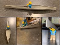
I wanted to try and model a person in the boat but it is not easy to visualize in CAD. Lego man has stubby legs and an enormous head, but when seated his hips/torso proportions are similar to mine. As long as I had the CAD file, I ran off a 1:25 scale boat on a 3D printer to better see what it looks like.

IMG_1724.JPG - Click image for larger version  Name:	IMG_1724.JPG Views:	1 Size:	154.2 KB ID:	93593
 
Last edited:
Neat Model !

I've seen the bottom of a friends racing Kayak, that was similar ! Round Bottom to about the mid section, then turned int a "V". He said it wasn't very stable, but fast !

Loving this So far !
Thanks !

Jim
 
That KAPER formula graph really rings a bell for me. When I compare speed in my J-200 (18'6") and my C1W (16'6") I'm always surprised that there is basically no difference in the left/middle of that graph -- i.e., at a moderate effort that would drive a touring solo at ~4.5-5.0 mph. The difference only appears in short runs (<=10k) when really putting the hammer down, and is quite modest. I ended up using the C1W for my first 340 last year, and I was happy with that choice.

A quick adjust seat height option could be very valuable. For people who single stick there's always an issue of getting the seat low enough for stability but not so low you can't effectively plant the paddle. It might also help with leg fatigue, which is often a problem with the surfski, sit-on-the-bottom folks.

Make sure Lego man doesn't forget his hat!
 
The epoxy viscosity is very sensitive to temperature. I can control small infusions using heating pads, etc, but a full boat would have to be done in the garage: I do have a radiant tube heater on the ceiling that I think will be enough to control temperature of the mold/infusion

This is way above my pay grade in complexity, but is humidity a concern?

My shop was a garage and has a concrete slab floor that stays cold/cool well into summer. When it gets warm out the humidity in the shop skyrockets. Right now; it’s 80F outside and even with the windows closed to retain some cool the humidity in the shop is 75%. If I opened the windows it would jump even higher.

I have to run a window AC unit for humidity control, and will need to install it soon.

AC unit, or a dehumidifier?
 
The epoxy viscosity is very sensitive to temperature. I can control small infusions using heating pads, etc, but a full boat would have to be done in the garage: I do have a radiant tube heater on the ceiling that I think will be enough to control temperature of the mold/infusion.

Have you considered using vinyl ester resin? It's much cheaper and much thinner.

Alan
 
Vinylester is cheaper and less viscous, but not by much- especially if temperature is controlled. The selling point for me is that the Adtech 820 epoxy has twice the tensile strength and 30% more flexural strength than vinylester resin: both significant improvements (if temp can be managed). Even among production infusion epoxies, Adtech has far and away the best cured strength characteristics: even better than (and cheaper than) west system pro-set. In terms of strength per unit weight or strength per unit cost, I think Adtech epoxy wins. (trying to use it for general epoxy repair sucks, though; because you need some way to heat it up or it won't cure!)

Both of my Northstar canoes are made of vinylester, so it can be assumed to be strong enough, but my best test results have thus far been with epoxy, so I feel most comfortable staying with that system. In comparing resins, most data sheets claim "room temp" cure at 77F, which is pretty warm! Ive had infusions fail at 67F, but if you can bump the mold temp to 85+ it makes all the difference.

As far as humidity goes, it doesn't matter a whole lot- as the vacuum infusion is close to a closed system. Dry fiber and PVC foam doesn't soak up much water. Most moisture is pulled out during the hour+ vacuum test "drop test" of the mold. If using a wood core in a humid environment though, you would have to pull vacuum on the layup for a longer time prior to infusion to evaporate moisture out of the wood before infusing the resin.

Winters in MN are fairly dry, but we will pull snowy cars into the heated garage: they melt all over the floor, but within a few hours the radiant heater will evaporate all the moisture off of the slab! The efficiency of radiant is incredible: we can open the double garage door and drive in/out and it doesn't even cycle.
 
Good to hear you're using 820 resin and have a good way to warm things up. The 820 is thinner than most but still a good bit thicker than vinylester. But when I was using it for infusion (and other tasks) I didn't have a way to heat the shop up that warm and I was doing it in the middle of winter. Nor did I realize it needed to be above 80 degrees to fully cure until I had a sticky hull and started doing more reading.

I didn't necessarily have trouble infusing with 820 but it sure was slow and had me nervous that it would start to set up before completely wetting out the part. Like you said I'm sure warming it up would have made a big difference. But that being said the vinyl ester resin had no problem at any temp.

I've got all my hull resistance data on another computer that's not being used right now. One of these nights I'll get a chance to fire it up and put up some numbers. That should help give some real world references between predictions and reality. I'm a Mac guy too so when I wanted to start using Delftship I snagged an out of use PC from work and set it up at home.

Alan
 
-I have never seen a Texas/Spencer canoe in person (and online searching shows only few photos and no real specifications), but I think this design is somewhere close to a Landick II.

Looks just like a Landick II. I have seen a few around the Safari. I have a friend that just had one built for the 2020 Safari.

muddyfeet looks like you and I are working on the same thing. I also have lots of help from Alan. Looking forward to seeing your build.
 
Time to get physical.

I just returned from a week up around Basswood Lake in the BW, where I napped in my hammock and thought about how I want to make the parting flanges for the canoe mold.
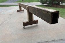
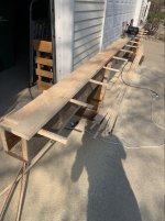
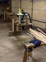
But anyway, the build has advanced from the digital realm to the physical world. I re-surfaced the back deck this spring, so I had a bunch of 16' 5/4 boards. They're mostly junk with a little rot- but I managed to find a few decent ones to make into a strongback. It is an 18' long box beam- put together with a ton of leftover 3.5" decking screws. The best feature is the wheels: 3" heavy duty casters with locking mechanisms. Moving it around the garage is effortless, and for now at least it seems fairly stable when locked.
IMG_1516.JPG

The next step is to make some strips. I have a belt-driven table saw in the garage (which sees more use as a table than as a saw), but I thought the Dodd-skillsaw method would be easier than feed ramps and fence adjustments. I just used 1x8 pine from menards and tried to pick some with the fewest knots. It worked alright, but I found that if the saw did start to 'wobble' and cut anything besides a straight line that it would only get worse the more you cut. So I ended up cutting strips from both sides and working towards the middle of the board. I used the thinnest ripping blade I could find and set it to cut 5/32 or so- and made a gigantic pile of dust, but kept it out of the garage. I got about 80 12' strips and 30 14' strips and a ton of shorties. Not sure how much is enough.

IMG_1517.JPG
 
Next, I milled the bead and cove to make the stripping go faster/easier. I used a 1/8 radius bit for the 5/32 strips and it worked fine. I mounted the router table to one end of the strongback and used the length of it as an outfeed ramp. Once I dialed in the router settings it was just a matter of feeding strips in for an hour or two. I needed the diagonal length of the garage to feed the 14' strips, so I did this at night while the family was sleeping. I did all the bead and cove in one stand so as to avoid setting it all up a second time, and then put the cars/bikes/lawnmower/etc back in the garage like nothing happened.

IMG_1745.JPG
 
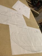
I printed out the plans to start cutting forms. Adobe will print large PDFs on multiple sheets as a ‘poster’ and will include alignment marks in the corners. I was worried about whether or not I could tape them together precisely enough, but I think everything came out with good enough alignment. I traced them onto MDF with carbon paper and was able to fit all but 3 on an 8x4 sheet. This took about 4 hrs of tracing lines: a lot longer than I thought. I have only started to cut them out. I can’t help but imagine that all this could be done easily and with much more precision using a cnc router. Heck, with the right machine I could skip stripping altogether and just mill a plug out of blocks of foam! C9D99E9B-D6DE-4742-96DB-FC7F61B5BB79.jpeg
 
Back
Top